Concession Application - Revised
NAWEP
Norwegian Airborne
Wind Energy Pilot
Concession application for an airborne wind energy plant at Lista Airport, Farsund Municipality
CONCESSION APPLICATION
NAWEP - Norwegian Airborne Wind Energy Pilot
Airborne Wind Energy Plant at Lista Airport, Farsund Municipality
Applicant: Kitemill AS (org. no. 992 943 718)
Date: 28 April 2026
Version: 2.0 - Revised following NVE (Norwegian Water Resources and Energy Directorate) feedback of 18.03.2026 (ref. 202421870-10)
NVE case number: To be assigned upon submission
1. SUMMARY
1.1 Project description
Kitemill AS is applying for a license to establish NAWEP (Norwegian Airborne Wind Energy Pilot) - an R&D project for airborne wind energy (AWE) at Lista Airport in Farsund municipality.
Key figures:
- Installed capacity (grid feed-in): 1.2 MW (12 production units of 100 kW each + 3 R&D units)
- Expected annual production: approx. 4.2 GWh at mature operation (3,500 full-load hours)
- Operating altitude: 150-500 metres above ground
- Plan area: approx. 1.5 km² within the airport's existing industrial area
- Project period: 2026-2031 (6 years: 2 years installation, 3 years operation, phased)
1.1.1 Plan area and operating area - delimitation
In line with NVE's feedback, the distinction between the plan area and the operating area is clarified:
-
Plan area: The geographically delimited area where physical interventions (ground stations, gravel pads, underground cable, new substation and transformer stations) are to be established. The plan area amounts to approx. 1.5 km² within Lista Airport's existing industrial area. This is the area to which the license specifically applies for physical development.
-
Operating area: The airspace in which the kites operate. The operating area extends beyond the plan area both horizontally (in accordance with CAA-N's danger area EN D257) and vertically (operating altitude 150-500 m). Airspace activity is regulated by Luftfartstilsynet's (Norwegian Civil Aviation Authority, CAA-N) operating permits (Appendix 04 and 05).
The plan area and operating area are therefore not identical. The operating altitude is described in section 4.6, and the airspace regime (danger area EN D257) in section 17.2.
1.2 Comparison with conventional wind power
Note: NVE's application template for wind power plants is designed for conventional turbines with permanent foundations and access roads. Airborne wind energy technology (AWE) has substantially different characteristics, and equivalent topics are addressed through descriptions of the ground station, service area, grid connection, operating pattern and operating restrictions in the relevant chapters.
| Aspect |
Conventional wind power |
AWE (Airborne wind) |
| Height |
Fixed tower height (typically 80-150 m) |
Operating altitude 150-500 m |
| Foundation |
Large concrete foundations |
Light ground station on steel frame |
| Roads |
Requires access roads |
No new roads necessary |
| Visual impact |
Permanent, static |
Visible only during operation |
| Flexibility |
Fixed location |
Can be landed/removed quickly |
1.3 Phased implementation
To uphold the precautionary principle (Norwegian Nature Diversity Act § 9), the project will be implemented gradually:
| Year |
Activity |
Systems |
| 2026 |
Test flying of R&D units, daytime only, monitoring programme established |
1-3 (R&D) |
| 2027 |
Installation of stations M, N, O under observation |
3 |
| 2028 |
Installation of stations A-L, grid connection, commissioning |
15 |
| 2029 |
Operating year 1 - full operation |
15 |
| 2030 |
Operating year 2 - continued operation and optimisation |
15 |
| 2031 |
Operating year 3 - termination and final evaluation |
15 |
1.4 Non-technical summary of the environmental impact assessment
In accordance with the EIA Regulations (Norwegian Environmental Impact Assessment Regulations) § 17, a brief non-technical summary of the environmental impact assessment is provided here. The full impact assessment is enclosed (Appendix 07).
Purpose of the project: To establish NAWEP as a pilot and demonstration plant for airborne wind energy (AWE) at Lista Airport. The primary purpose is knowledge building about the technology, not large-scale power production.
Impacts on the environment and society:
- Landscape: Moderate and temporary visual impact. AWE kites are only visible in the air during operation; the ground stations are low and discreet. Reversible at project end.
- Noise: Dominant frequencies 1,500-2,000 Hz, high-frequency. Calculated Lden at the nearest dwelling (Nordhassel and Råstad, approx. 770 m from the nearest ground station) is expected to be below the threshold value Lden 45 dB(A). No dwellings within the Lden 45 contour based on population data.
- Birds and migratory birds: Potentially the most sensitive impact. Addressed through phased ramp-up, operational shutdowns during migration periods and a continuous monitoring programme. A professional assessment for 15 simultaneous systems has been prepared by Arnold Håland/NNI Resources.
- Biodiversity: The plan area is already heavily affected by airport activity; no new areas are affected. Indirect impacts on Nesheimsvatnet (approx. 1.4 km) and Slevdalsvannet (approx. 330 m) nature reserves are assessed as limited.
- Cultural heritage: No direct interventions in protected cultural heritage. Visual impact on WW2 remains and Nordberg fort is assessed as acceptable.
- Public health and living environment: Limited impact owing to distance to settlements and noise profile.
- Electronic communications: Limited impact. Commitment to mitigation measures in the event of interference.
- Water and ground pollution: Low risk. Standard emergency preparedness routines established.
- Norwegian Armed Forces: Constructive dialogue established with the Armed Forces' Drone Services.
- Aviation: Established danger area EN D257 and ongoing cooperation with Lista Airport and CAA-N.
Comparison with the zero alternative: Against the zero alternative (no development), NAWEP delivers +4.2 GWh/year of renewable energy (equivalent to approx. 270 households), +630 t CO2e/year of climate savings, 76-85 MNOK in direct regional investment and secured EUR 3.35M+ in EU funding (Innovation Fund, Horizon Europe, MSCA, HaDEA), against a permanent land use of only 0.05 hectares (520 m²) — fully reversible at project end. Industrial-scale impact: NAWEP is the precursor to Kitemill's FJORD factory (EUR 35M EU IF Clean Tech Manufacturing application, submitted 23.04.2026), which at mature operation provides 1,330 FTE and 176 MW annual production capacity, with Lista as a candidate location and a Norwegian supplier sector for winches, composites, tethers and power electronics. See section 19.4 for the full quantitative balance of benefits and drawbacks.
Mitigation measures: Gradual ramp-up, operational shutdowns during migration periods, continuous monitoring, measurement programmes for noise and birds, automatic flight termination with return-to-home, and documented reporting to authorities. See chapter 20.
Uncertainty: The knowledge base for AWE under Norwegian conditions is limited. The principal purpose of NAWEP is to build this base. All assessments reflect the precautionary principle, and the project may be adjusted or terminated if consequences are unacceptable.
1.5 Strategic significance
Airborne wind energy technology (AWE) represents a new approach to wind power production in which a wing profile operates in higher air layers (200-500 m) with access to stronger and more consistent wind resources than conventional turbines. The technology is still immature and under active international development, but efforts are under way through, among others, IEA Wind Task 48 and the EU's Horizon Europe programme to bring it towards commercial maturity.
International context. AWE is recognised as an emerging technology within several European and international frameworks:
- IEA Wind TCP Task 48: Eleven countries, including Norway, cooperate on research and development of AWE technology through the International Energy Agency (IEA).
- EU funding: The NAWEP project is supported by the EU Innovation Fund (EU ETS), Grant No. 101038892. In addition, Kitemill participates in several other EU-funded projects that strengthen the company's technology development: AWE-KM2 (Horizon Europe, Grant No. 101189207), AWETRAIN doctoral network (Marie Skłodowska-Curie Actions, Grant No. 101168734) and 3D-Circular (European Health and Digital Executive Agency, Grant No. 101226256).
- Regulatory development: In 2024, Germany introduced the world's first feed-in tariff for AWE systems through its Erneuerbare-Energien-Gesetz (EEG), marking a transition from pure research to early commercialisation.
National context. The Norwegian Energy Commission's report "Mer av alt - raskere" (NOU 2023:3) points to the need for at least 40 TWh of new power production by 2030. DNV's analyses (2024, 2025) indicate that Norway may become a net importer of electrical power in the early 2030s, with demand growth exceeding new development. At the same time, the development of conventional onshore wind power has met significant challenges related to land use, environmental interventions and local opposition. AWE technology has the potential to contribute to power production with substantially lower land requirements and material consumption than conventional alternatives, but this requires further technology development and documentation through projects such as NAWEP.
Potential of the technology at maturity. Although the technology is currently at an early stage, the fundamental physical and system characteristics suggest that mature AWE technology can offer substantial advantages compared with conventional wind power:
- Access to stronger and more stable wind resources at higher altitudes
- Substantially lower material consumption per unit of energy produced
- Minimal ground footprint compared with conventional turbines
- No permanent terrain interventions - movable installations
- Lower visual exposure
These properties are based on the system's physical operating principle and the company's calculations, and will be verified through the NAWEP project.
From complementary to primary alternative. In the maturation phase, where NAWEP is positioned, AWE is a natural complement to established renewable technologies. At technological maturity, however, AWE can evolve into a primary alternative that directly addresses the principal bottlenecks in deployment of conventional wind power in Norway:
- Licensing and local acceptance: Lower visual signature, absence of tall permanent towers and concrete foundations, and reversibility at project end reduce typical reasons for local opposition and simplify the licensing process.
- Nature interventions: Minimal permanent land use (cf. sections 7.3 and 19.4.1), no access roads, and no permanent terrain interventions result in substantially lower impact on biodiversity and landscape.
- Energy production: Access to stronger and more stable winds at 200-400 m operating altitude provides a higher capacity factor than ground-mounted alternatives at the same location, and access to wind resources across a substantially larger geographical area where conventional wind power is not currently economical or acceptable.
- Material use and circularity: Substantially reduced structural material per MW (estimated ~80-90 % less than HAWT of the same capacity) and no concrete foundations result in lower embodied CO2 and easier decommissioning.
NAWEP is the technical maturation platform that enables this transition. The timeframe for when AWE in Norway can move from complement to primary alternative depends on technological maturation, regulatory framework and industrial scale-up (cf. sections 19.4.5 and 19.4.6).
FACT BOX: NAWEP in brief
- Applicant: Kitemill AS (org. no. 992 943 718)
- Location: Lista Airport, Farsund municipality
- Technology: Airborne Wind Energy (AWE) - airborne wind power plant
- Capacity: 1.2 MW installed (15 x 100 kW systems)
- Annual production: 4.2 GWh at mature operation
- Plan area: approx. 1.5 km² within the airport's industrial area
- Permanent land take: approx. 520 m²
- Project period: 2026-2031
- Purpose: R&D and knowledge building for airborne wind technology
2. ABOUT THE APPLICANT AND PROJECT
2.1 Applicant
Kitemill AS
Org. no.: 992 943 718
Address: Flyplassveien 40, 4560 Vanse
Contact person: Thomas Hårklau, CEO
E-mail: th@kitemill.com
Kitemill AS is a Norwegian limited company with organisation number 992 943 718.
Major shareholders as of 12.09.2025:
| Shareholder |
Registered shares |
Fully diluted* |
| Ignatia AS |
33.6% |
30.3% |
| En-Vision Europe Ltd |
16.2% |
14.8% |
| Andre Polderman (3 subscription tranches) |
- |
8.1% |
| Bjørkehagen AS |
5.1% |
4.6% |
| Nanna Gjerde Invest AS |
4.7% |
4.2% |
| Kongsberg Innovasjon AS |
3.9% |
3.5% |
| Nannok Invest AS |
3.4% |
3.0% |
| Other shareholders (dispersed) |
33.1% |
31.5% |
*Fully diluted includes Funding Round 1, stock options and outstanding warrants.
Board of Directors:
- Jérôme Guillet (Chair)
- Åslaug Marie Haga
- Jon Gjerde
- Svein Olav Torø
Management:
- Thomas Hårklau - CEO
- Marius Dyrset - CTO
- Asgeir Lønø - CFO
Group structure: Kitemill AS has two wholly owned subsidiaries that function as special purpose vehicles (SPV) without employees:
- NAWEP AS - SPV for the airborne wind power project at Lista (the subject of this concession application)
- Exact Aircraft AS - SPV
The company has no parent company.
2.2 Background
Kitemill AS is a Norwegian technology company founded in 2008, with R&D headquarters at Lista Airport. The company develops airborne wind energy technology (AWE) which exploits stronger and more consistent winds at higher altitudes.
2.3 Project objectives
NAWEP is primarily a research and development (R&D) project with the following main objectives:
- Demonstrate AWE technology under Norwegian climatic and regulatory conditions
- Document and assess environmental impact, with particular emphasis on birds and migratory birds
- Develop operating protocols for coexistence between AWE operation and natural values
- Establish a knowledge base for future commercial roll-out of the technology
- Contribute to increased knowledge of birds and migratory birds at Lista, including spring migration and AWE-specific bird behaviour
Knowledge building: The applicant has the stated goal of contributing to knowledge building both before and throughout the project period. This entails systematic collection and sharing of data on bird activity, the technology's impact and the effect of mitigation measures. All collected knowledge will be shared with relevant authorities and contribute to the overall knowledge base for AWE technology in Norway.
The project is co-financed by the EU, reflecting the project's relevance within the EU's framework for energy transition.
2.4 Societal benefits
2.4.1 Regional energy situation
Southern Norway (price area NO2) has in recent years experienced the highest electricity prices in the country. In December 2024, the spot price in NO2 reached NOK 13.16/kWh (Nord Pool), among the highest registered for the price area, and throughout 2025 prices in southern price areas have been many times higher than in Northern Norway. The cause is limited transmission capacity between north and south, combined with export through interconnectors.
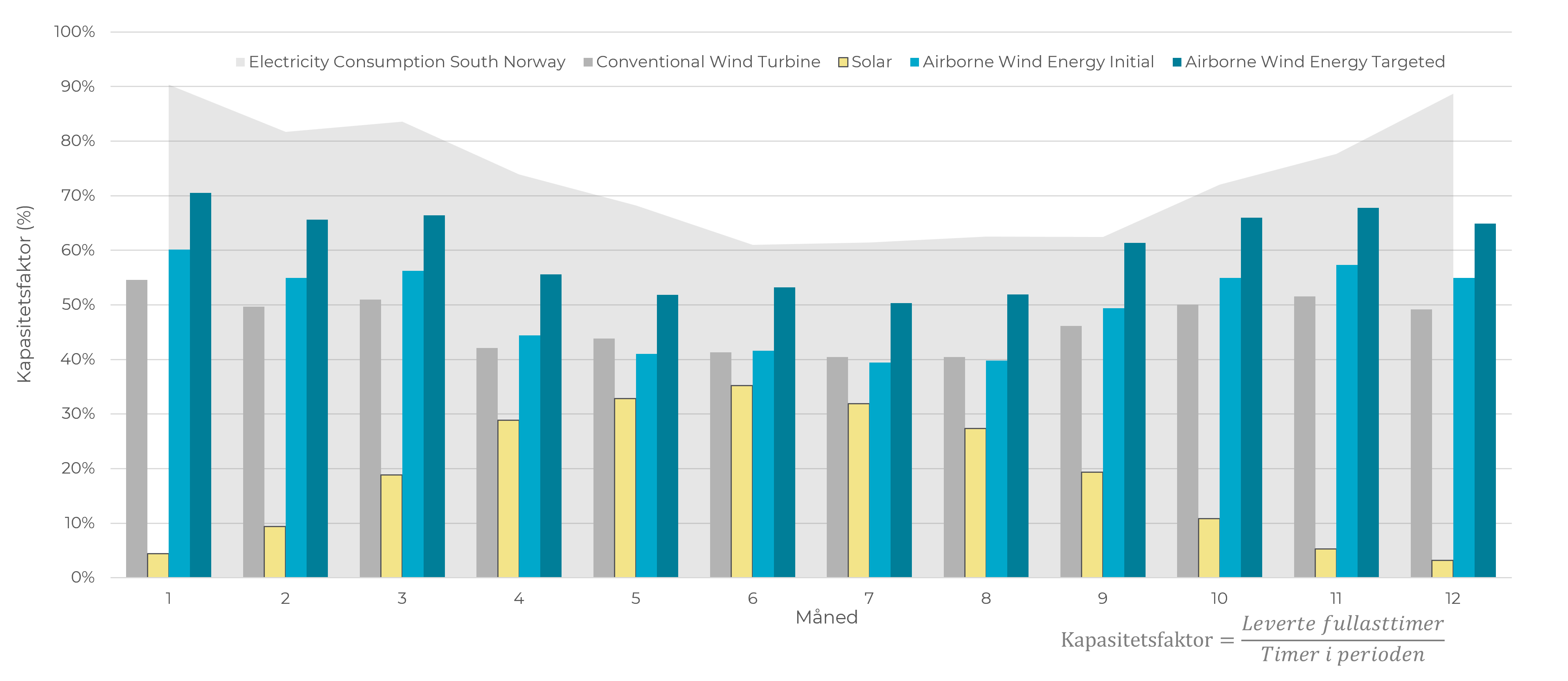
Any new local power production in the region contributes directly to strengthening security of supply and dampening price pressure. The NAWEP project, with its 1.2 MW installed capacity and expected annual production of up to 4.2 GWh at mature operation, will provide a limited but real contribution to regional power production. The project's primary value in this context is, however, the knowledge it generates regarding AWE technology's suitability for large-scale roll-out in the region.
The production profile of AWE technology has properties relevant to security of supply. The figure below shows the monthly capacity factor for AWE compared with conventional wind power and solar energy, set against electricity consumption in Southern Norway. AWE achieves a higher capacity factor than conventional wind power throughout the year, and the production profile follows the consumption curve more closely than both solar and conventional wind. Solar energy has the highest capacity factor in summer when consumption is lowest, while AWE has the highest production in the winter half-year when consumption and prices are highest. This complementarity makes AWE technology relevant to security of supply in Southern Norway.
2.4.2 Local value creation
The project entails direct local activity through:
- Kitemill AS has its R&D headquarters and workshop at Lista Airport with permanent employees
- Installation, operation and maintenance of 15 ground stations over the project period
- Construction of grid connection and internal infrastructure in cooperation with local suppliers
- Cooperation with Farsund municipality, landowners and local stakeholders
2.4.3 Knowledge building and industrial development
Kitemill is among a limited number of active AWE developers globally that combine long-term field testing, regulatory engagement and participation in international research and coordination frameworks. The company participates in several EU-funded research and innovation projects and is an active participant in international AWE coordination through IEA Wind TCP Task 48. In contrast to many AWE initiatives that are primarily laboratory- or model-based, Kitemill's work is characterised by long-term outdoor operation, licensing processes and engagement with grid, aviation and environmental authorities. This gives Kitemill a relevant role as a reference for applied and deployment-oriented AWE development, complementing more academically oriented initiatives within the field.
The project contributes to knowledge building at several levels:
- Technical: Documentation of system performance, availability and production under Norwegian conditions
- Environmental: Systematic collection of data on coexistence with birds and natural values
- Regulatory: Experience base for the development of Norwegian regulations for AWE technology
- Industrial: Development of value chain, supplier network and competence environment
2.4.4 European and global context
The EU Innovation Fund has awarded the project EUR 3.35 million, reflecting an assessment of the project's relevance for European energy transition. The EU's climate framework (Fit for 55, RED III) sets a target of at least 42.5% renewable energy by 2030, and the EU needs an estimated 510 GW of wind power capacity to achieve this target. AWE technology can in time complement conventional wind power, particularly in areas where traditional development encounters land-use constraints.
Norway's climate commitments (55% reduction by 2030, 70-75% by 2035) require a significant increase in renewable power production. NAWEP contributes to developing a technological alternative that, at maturity, can make a substantial contribution to this transition.
2.4.5 Societal benefit and technology maturation
NAWEP represents a technology maturation project with a broader societal perspective than pure energy production. Kitemill's early-phase systems have commercial applications beyond power production, contributing to the maturation and financing of the technology towards its ultimate role as a large-scale renewable source.
Civil emergency preparedness and services:
- Protection of critical infrastructure through continuous airspace presence (ISR - Intelligence, Surveillance, Reconnaissance)
- Monitoring of environmental emissions, including emissions from ports, industry and transport
- Monitoring and early warning of forest fires and other natural events
- Support to rescue services through persistent monitoring during incidents
- Communications support in areas with poor coverage
Portable renewable energy:
AWE differs fundamentally from conventional wind and solar power in that the production plant can be moved. A KM2 plant produces annual energy equivalent to 12-15 truckloads of diesel. This opens up applications that are not possible with ground-fixed renewable solutions:
- Temporary energy supply during natural disasters
- Energy for forward operating bases and operations
- Power supply in areas without grid
- Emergency power with significantly higher production than conventional generators
Technology maturation pathway: These applications represent important maturation steps that gradually qualify airborne wind technology. Each application contributes to additional flight hours and a larger data base, further development of control algorithms and safety functions, cost reduction through volume effects, and the establishment of regulatory pathways for AWE.
Energy as a long-term goal: Once the technology is qualified through commercial early-phase applications, it will be deployable at large scale as renewable energy production at sites where conventional wind power is not feasible or desirable. This may contribute substantially to Norway and the EU recovering ground towards their net-zero ambitions, with airborne wind as a complement to ground-mounted wind power and solar energy. The NAWEP project at Lista is therefore not only a power development project, but a strategic technology development measure with significant societal benefit throughout the qualification phase.
3. MUNICIPAL ANCHORING AND PROCESS
See Appendix 33: Contact persons and stakeholders (EXEMPT FROM PUBLIC ACCESS)
The municipality's case officer for Kitemill's original dispensation application in 2018 has knowledge of the project from an early stage.
3.2 Dialogue and start-up meetings
Kitemill has had ongoing dialogue with Farsund municipality since 2017. Key milestones are summarised below:
| Date |
Meeting/Event |
Participants |
Decision/Conclusion |
| 12.12.2017 |
Application for temporary test plant |
Kitemill AS |
Submitted to the municipality |
| 22.03.2018 |
Technical Committee, case 18/41 |
Thomas Hårklau briefed |
Unanimously approved with conditions on bird monitoring |
| Feb 2025 |
Invitation to dialogue meeting v1 |
Kitemill, Farsund municipality |
NAWEP project presented |
| 14.03.2025 |
Dialogue meeting Lista Airport |
Kitemill, Farsund Lufthavn AS |
Lease agreement discussed |
| 28.03.2025 |
Application for temporary dispensation for demonstration plant |
Kitemill AS |
Submitted to the municipality |
| 17.06.2025 |
Technical Committee, case 61/25 |
Jan Hornung briefed |
Unanimously adopted with conditions |
3.3 Zoning plan and municipal decisions
Lista Airport is regulated through the Municipal sub-plan for Lista flight and business park.
Zoning purposes:
- Airport (main purpose)
- Industrial and business purposes
- LNF (Agriculture, Nature and Outdoor Recreation) areas (adjacent)
Decisions for Kitemill:
Current decision - Technical Committee 17.06.2025 (case 61/25):
"Pursuant to the Planning and Building Act § 7, dispensation is granted from the airport zoning purpose in the municipal sub-plan for Lista flight and business park with a view to establishing a demonstration plant for wind power technology. The application is approved on the following conditions:
- The test period shall contribute to increasing the knowledge base regarding the technology's impact and consequences for birds. Before testing is initiated, a plan shall be submitted on how the level of knowledge can be increased, for approval by the municipality. The plan shall be submitted to the County Governor of Agder for input prior to approval.
- During testing there shall be an adequate level of personal safety. Other public authorities are required to confirm that an adequate safety level is in place."
- Archive case no.: 25/00659-5
- Form of decision: Unanimously adopted following the Chief Municipal Executive's recommendation
Justification from the municipality:
- The advantages of granting the dispensation are assessed as clearly greater than the disadvantages, cf. Planning and Building Act § 19-2
- The measure is of a temporary nature and consists of measures that are reversible and movable
- Contribution to new technology that may entail energy production with less environmental intervention than current wind technology
- Bird monitoring is required as part of the approval
In the municipal processing, statements were obtained from the CAA-N, the County Governor of Agder, neighbours and Farsund Lufthavn AS. All statements, neighbour comments and the developer's comments are publicly available in the municipality's case documents (archive case 25/00659-5).
Earlier decision - Technical Committee decision 22.03.2018 (case 18/41):
Kitemill has had a dispensation for test flying at Lista Airport since 2018. The original decision concerned a temporary kite test plant and was adopted unanimously with conditions on bird monitoring (archive case no. 2017/2456). The 2025 decision replaces and extends this dispensation to encompass the demonstration plant.
3.4 Schedule
Project phases
| Year |
Phase |
Activity |
Systems |
| 2026 |
Preparation |
Licensing process, test flying of R&D units, monitoring programme established |
1-3 R&D |
| 2027 |
Installation phase 1 |
Installation of stations M, N, O. Start-up of monitoring programme (field campaigns) |
3 |
| 2028 |
Installation phase 2 |
Installation of stations A-L, grid connection completed, commissioning |
12 (+3 = 15) |
| 2029 |
Operating year 1 |
Full operation with 15 systems, operational shutdown during the busiest migration periods |
15 |
| 2030 |
Operating year 2 |
Continued operation, evaluation and optimisation |
15 |
| 2031 |
Operating year 3 |
Final operating year, end evaluation and reporting |
15 |
GANTT chart
Activity                           2026        2027        2028        2029        2030        2031
                                   Q1 Q2 Q3 Q4 Q1 Q2 Q3 Q4 Q1 Q2 Q3 Q4 Q1 Q2 Q3 Q4 Q1 Q2 Q3 Q4 Q1 Q2 Q3 Q4
─────────────────────────────────────────────────────────────────────────────────────────────────────────────
LICENSE AND PERMITS
  Concession application NVE       ████████████████
  Aviation permit                  ████████████████████████
  Grid connection agreement                    ████████████████

PREPARATION
  Test flying of R&D units         ░░░░░░░░████████████████
  Bird monitoring established          ████████████████────────────────────────────────────────────────────

INSTALLATION
  Stations M, N, O (3 units)                   ░░░░████████
  Stations A-L (12 units)                              ░░░░████████████████
  Grid connection and commissioning                        ████████████

OPERATION
  Year 1 - Full operation (15 systems)                                 ████████████████
  Year 2 - Operation and optimisation                                                  ████████████████
  Year 3 - Termination and evaluation                                                                  ████████████████

MONITORING AND REPORTING
  Field campaigns birds               --          --          --          --          --
  Annual reporting to NVE                                  ▲           ▲           ▲           ▲
  Final evaluation                                                                             ████████
─────────────────────────────────────────────────────────────────────────────────────────────────────────────
Legend: ████ = Main activity  ░░░░ = Preparation  ──── = Ongoing  ▲ = Milestone  -- = Field campaign (see chapter 9.7)
Main milestones (from EU Innovation Fund NAWEP)
| Milestone |
Description |
Planned |
| MS9 |
All permits granted |
Q2 2027 |
| MS12 |
Financial close |
Q2 2027 |
| MS15 |
Construction works completed |
Q4 2028 |
| MS16 |
Grid connection completed |
Q4 2028 |
| MS17 |
Commissioning |
Q4 2028 |
| MS18 |
Operating year 1 completed |
Q4 2029 |
| MS19 |
Operating year 2 completed |
Q4 2030 |
| MS20 |
Operating year 3 completed, project termination |
Q4 2031 |
3.5 Local vs. regional handling
The project is processed by NVE as the licensing authority under the Energy Act (Norwegian: energiloven). Farsund municipality has adopted a dispensation from the zoning purpose in the municipal sub-plan (cf. section 3.3).
The County Governor's appeal and parallel process
The County Governor of Agder advised against the dispensation in its consultation statement (9 May 2025), referring to bird interests and the knowledge base, and appealed the decision after the municipality made its decision on 17 June 2025. The appeal is under processing.
Farsund municipality has upheld its decision following an overall assessment in which the administration emphasised, among other things:
- That the measure is temporary and reversible
- That the main purpose is to increase the knowledge base regarding new technology
- That studies of practical use in an area with abundant birdlife is a good way of increasing the knowledge base
CAA-N issued a positive consultation statement on 8 May 2025 (ref. 25/18542-2, signed by Section Head August Holte). The statement confirmed that Kitemill holds a valid operational authorisation in the specific category, that the planned activity is compatible with the existing danger area regime (END257) at Lista, and that the dispensation raises no objections from an aviation perspective. The statement is publicly available in full in Farsund municipality's case archive (case 25/00659-5, cf. Appendix 06).
All case documents, including the County Governor's statement and appeal, CAA-N's positive statement (ref. 25/18542-2), neighbour comments and the developer's comments, are publicly available in the municipality's archive (archive case 25/00659-5, cf. Appendix 06).
NVE has confirmed that the licensing process can proceed in parallel with the appeal case before the County Governor. The applicant acknowledges the County Governor's concerns regarding birds, and notes that the project's phased approach and monitoring programme (cf. section 9) is designed precisely to address the knowledge gap and document the technology's impact on birds under Norwegian conditions.
4. MAPS AND DELIMITATION
4.1 Overview map - Regional context
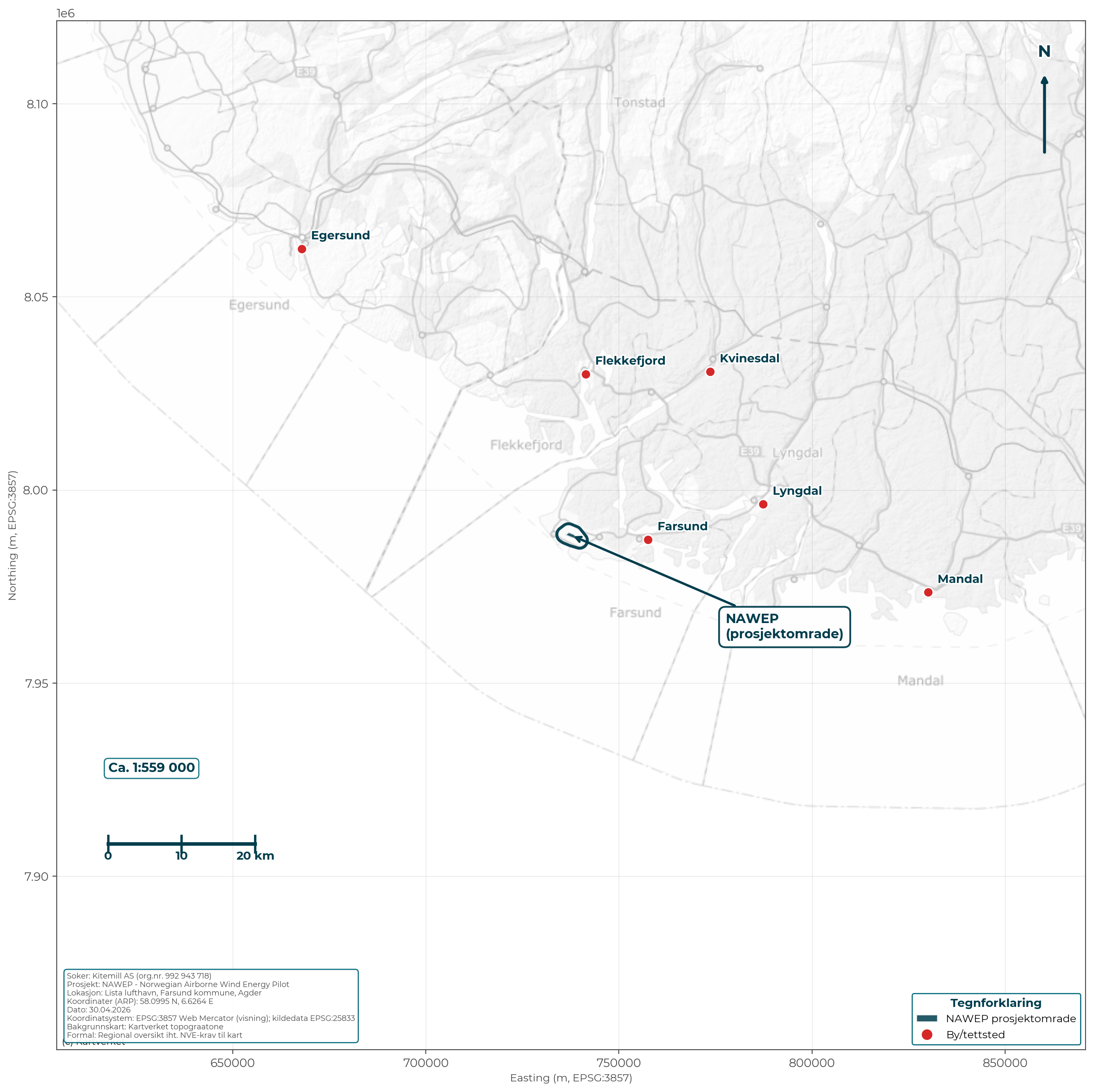 Figure 4.1: Regional overview map showing the project area's location in the Lister region, Agder. The ground stations (NAWEP) lie at Lista Airport west of Farsund. The map is NVE-suitable with compass needle, scale, legend, date, applicant and coordinate system.
Location:
- Coordinates: 58.0995° N, 6.6264° E (centre of the airport)
- Municipality: Farsund (municipality no. 4206), Agder county
- Region: Lister region, Southern Norway
- Distance to nearest town: Farsund centre approx. 8 km
Regional significance:
Lista Airport is located on the Lista peninsula, Norway's southernmost peninsula. The area has good wind resources and an extensive ornithological observation history, contributing to the knowledge base for assessing airborne wind technology in the area.
4.2 Local overview map
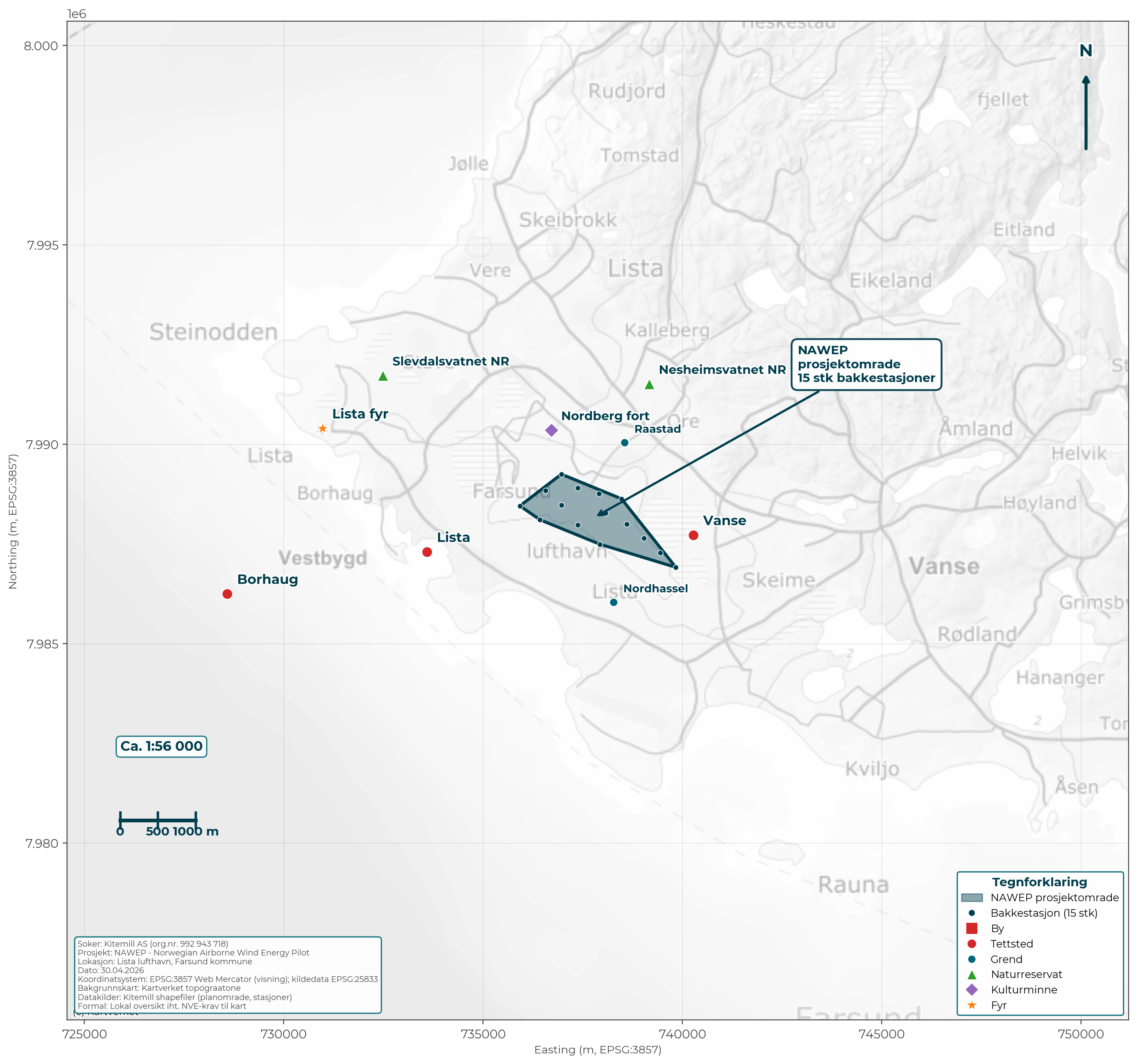 Figure 4.2: Local overview map showing the operating area at Lista Airport in relation to nearby population centres (Lista, Vanse, Borhaug, Farsund), hamlets (Nordhassel, Råstad), nature reserves (Slevdalsvannet, Nesheimsvatnet) and cultural heritage (Nordberg fort, Lista lighthouse). The map is NVE-suitable with all required elements.
Surroundings:
- North/north-east: Agricultural land, West Lista cultural landscape, Råstad hamlet, Nordberg fort (museum)
- East: Lundevågen, Borhaug population centre
- South: Nordhassel hamlet, Lista beaches, the North Sea
- West: Slevdalsvannet nature reserve, Lista population centre
4.3 Plan delimitation, station locations and grid connection
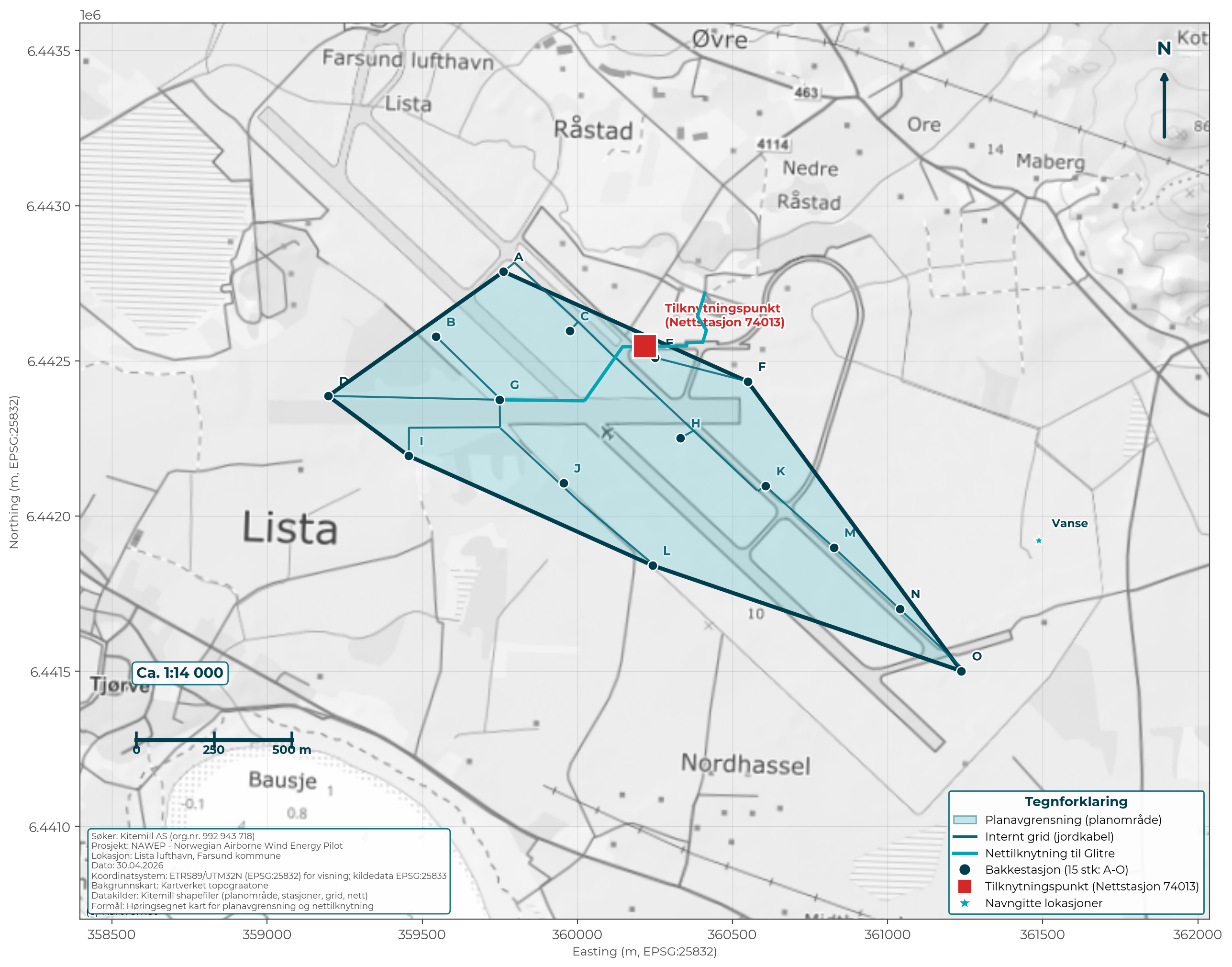 Figure 4.3: Consultation-suitable NVE map showing proposed plan delimitation (light cyan), 15 ground stations (A-O), internal grid (underground cable), grid connection to Glitre Nett, and connection point at upgraded substation 74013. The map satisfies NVE's general map requirements (north arrow, scale, date, legend, applicant's name, coordinate system, and Kartverket (Norwegian Mapping Authority) topographic background).
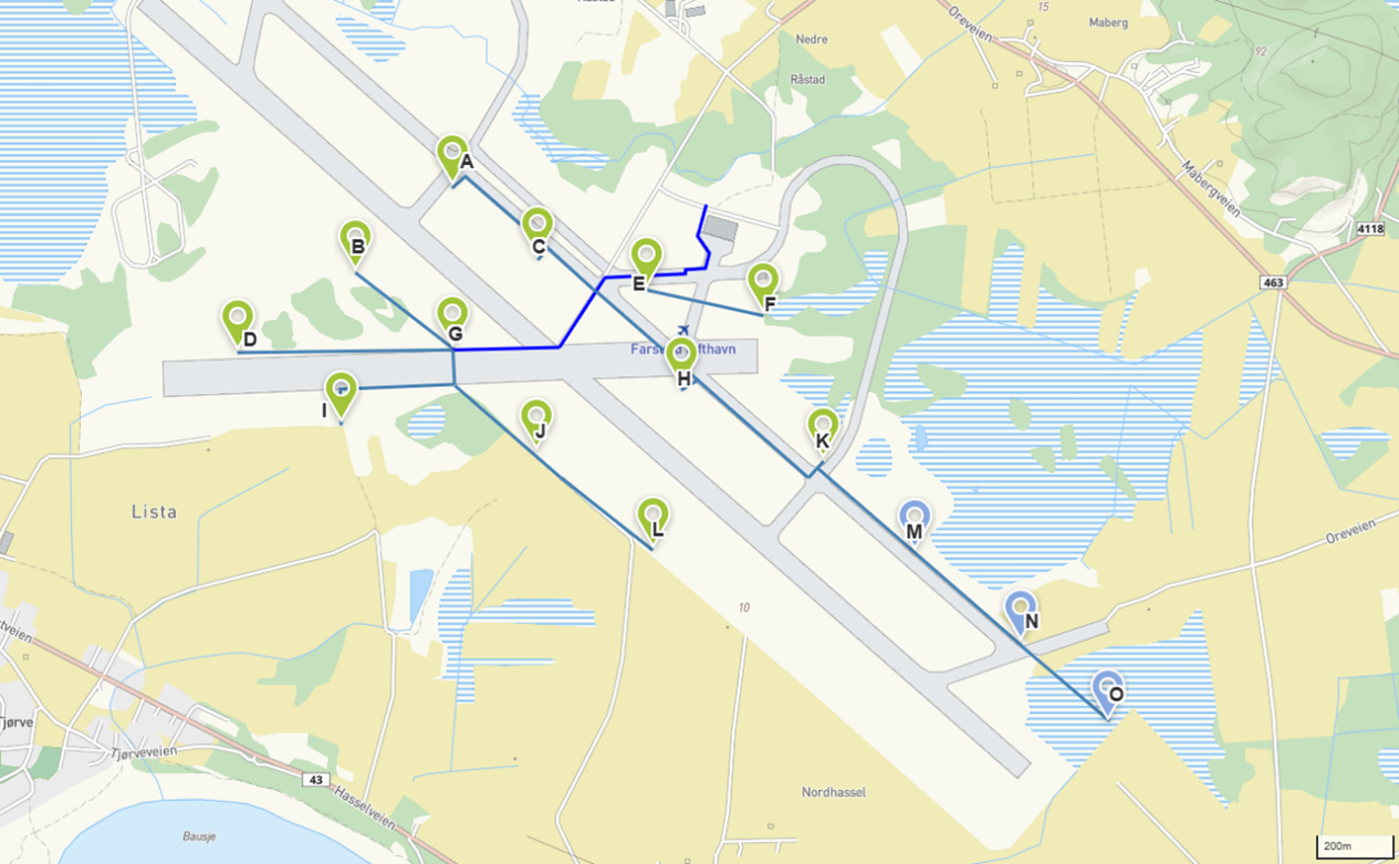 Figure 4.3b: Illustration from project phase 1 of station locations (A-O) with internal grid infrastructure. The NVE-suitable version above (Figure 4.3) is the authoritative version.
The plan area encompasses:
- Existing airport area within the fenced area
- Total approx. 1.5 km² (150 hectares)
- 15 possible station locations marked A-O
- Central connection point at point E (near terminal building)
KML files (can be opened in public map services):
- GRIDtegninger21.02.2025v1 m FoU punkt.kml - Grid layout with R&D point
- Operasjonsområdet tegninger6.11.2024.kml - Operating areas
- 250225_DangerArea.kml - Danger area (airspace)
4.4 Map with settlements and infrastructure
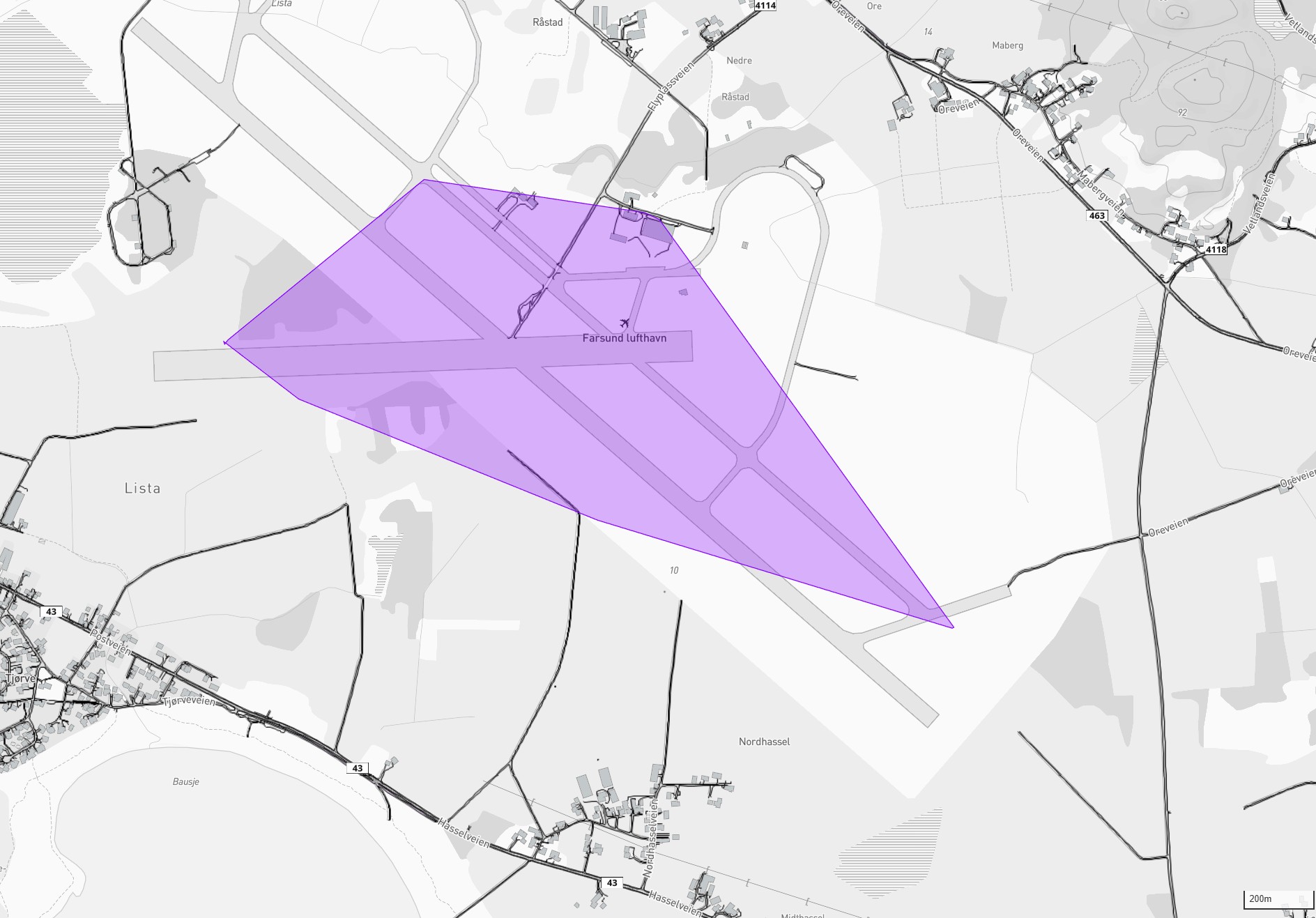 Figure 4.4: Detail map showing the operating area (purple) in relation to buildings, roads and other infrastructure. Lista population centre west of the airport, Nordhassel south.
Nearest settlements:
| Place |
Direction |
Distance from nearest station |
| Nordhassel (individual dwellings) |
South |
approx. 770 m (from station N) |
| Råstad (individual dwellings) |
North/north-east |
approx. 776 m (from station F) |
| Lista population centre |
West |
approx. 1,400 m (from station D) |
| Vanse centre |
North-east |
approx. 3,000 m |
| Borhaug population centre |
West |
approx. 4,000 m |
| Farsund town |
East |
approx. 8,000 m |
Road infrastructure:
- County road 43 (Listaveien) - south of the airport
- Flyplassveien - internal access
- No new roads required for the project
4.5 Map with environmental considerations
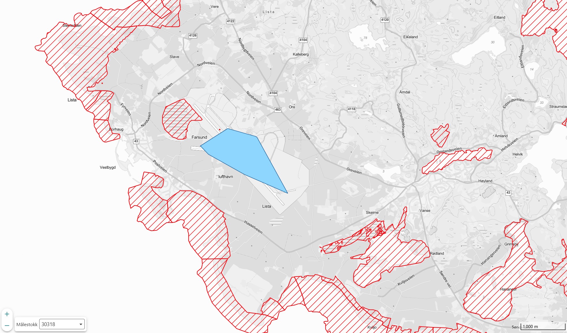 Figure 4.5: Operating area (blue) in relation to all protected areas in the region (red hatched areas). The map shows the project area's position in relation to protected areas. The project area does not overlap with protected areas.
Protected areas in the vicinity:
| Protected area |
Type of protection |
Distance |
Direction |
| Slevdalsvannet nature reserve |
Nature reserve |
approx. 330 m |
West |
| Lista wetland system |
Ramsar |
Adjacent |
South/West |
| Lista beaches |
Landscape protection area |
approx. 500 m |
South |
| Nesheimsvatnet |
Nature reserve |
approx. 1.4 km |
South-east |
Buffer zones:
No station locations are within the boundaries of protected areas. The minimum distance to Slevdalsvannet nature reserve is approx. 330 m (from station D).
4.6 Operating altitude
Note: For conventional wind power, tip height (the highest point of the rotor blade) is normally given. For AWE systems, the operating altitude (the height at which the kite flies during production) is the relevant measure.
| Parameter |
Value |
| Minimum operating altitude |
150 m above ground |
| Maximum operating altitude |
500 m above ground |
| Typical operating altitude |
200-400 m |
| Ground station height |
approx. 3 m |
4.7 Roads and infrastructure
Note: AWE technology does not require access roads, in contrast to conventional wind power plants.
The project utilises existing infrastructure at the airport:
- Existing asphalt runways and taxiways
- Existing roads to the airport area
- No new roads planned
4.8 Noise zone map
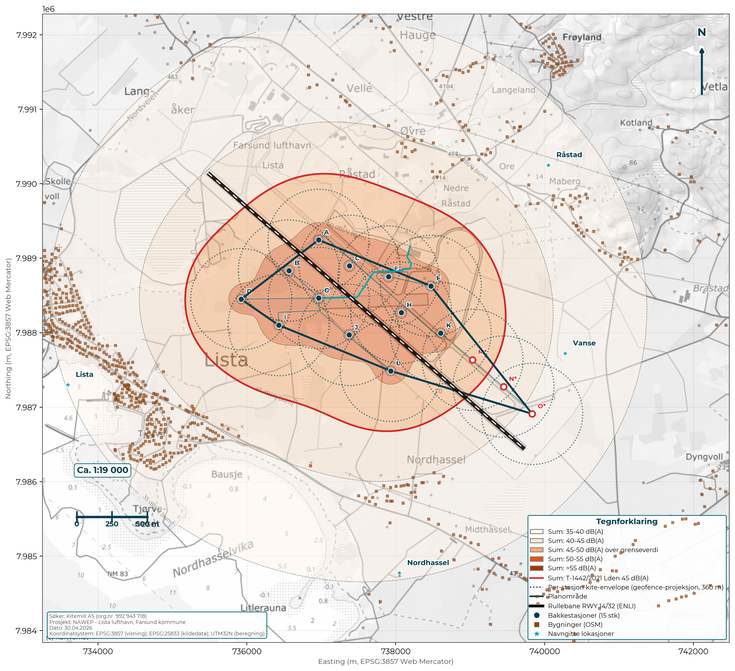 Figure 4.8: Noise zone map NAWEP. Dashed circles show per-station Lden 45 dB(A) radius (540 m). Filled contours show aggregated Lden from 15 units. The difference documents the summation effect of multiple simultaneous sources (+11.8 dB). Red line: T-1442/2021 (Norwegian noise-in-land-use-planning guideline) threshold value. See chapter 11.4 for full method.
4.9 Population density and SORA classification
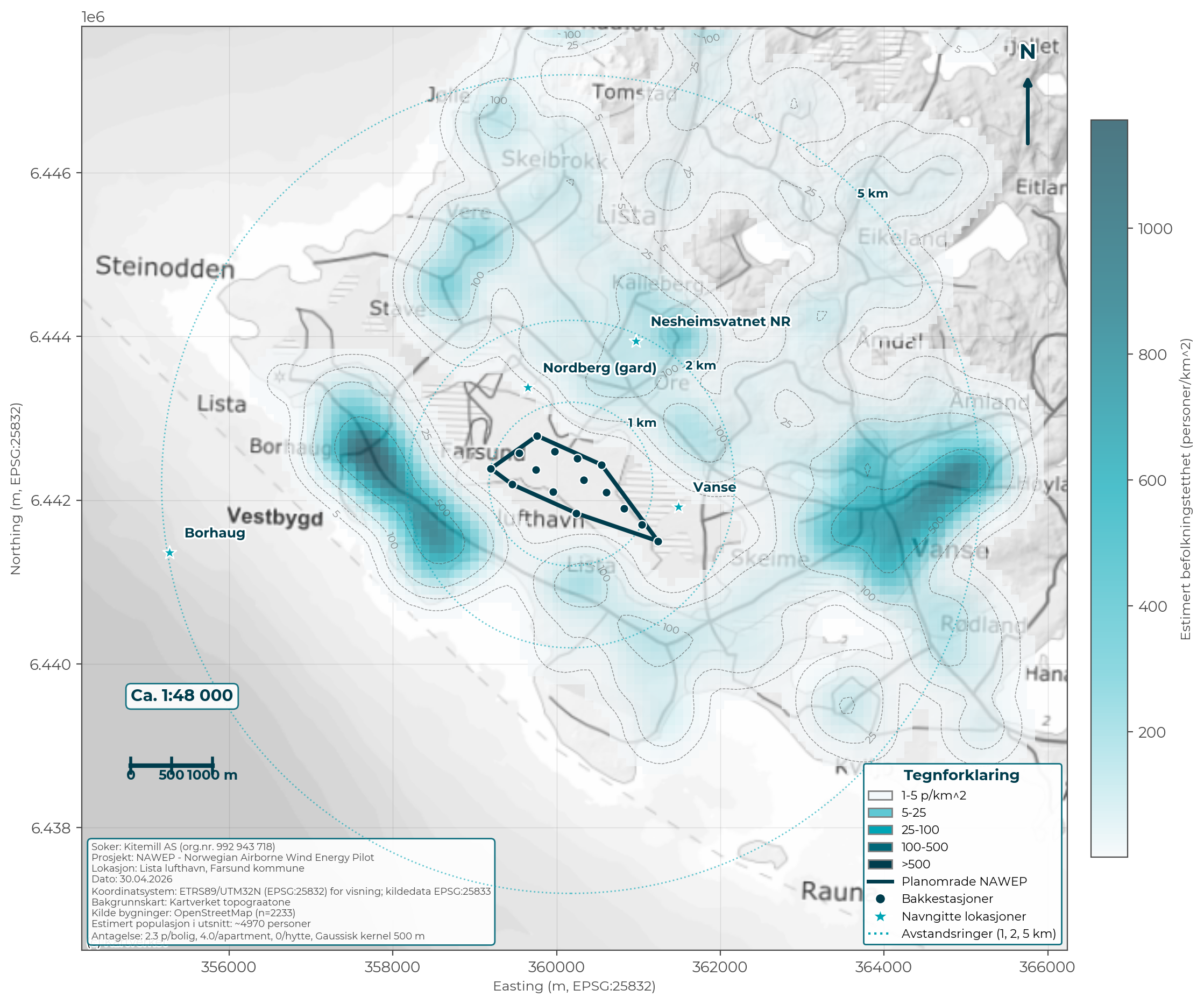 Figure 4.9: Estimated population density around NAWEP based on OSM building data and an assumption of average household size. Documents that the operating area and adjacent area are "Sparsely populated" in accordance with Kitemill's BVLOS operating permit. Population centres (Borhaug, Vanse, Farsund) lie 5-7 km from the plan area.
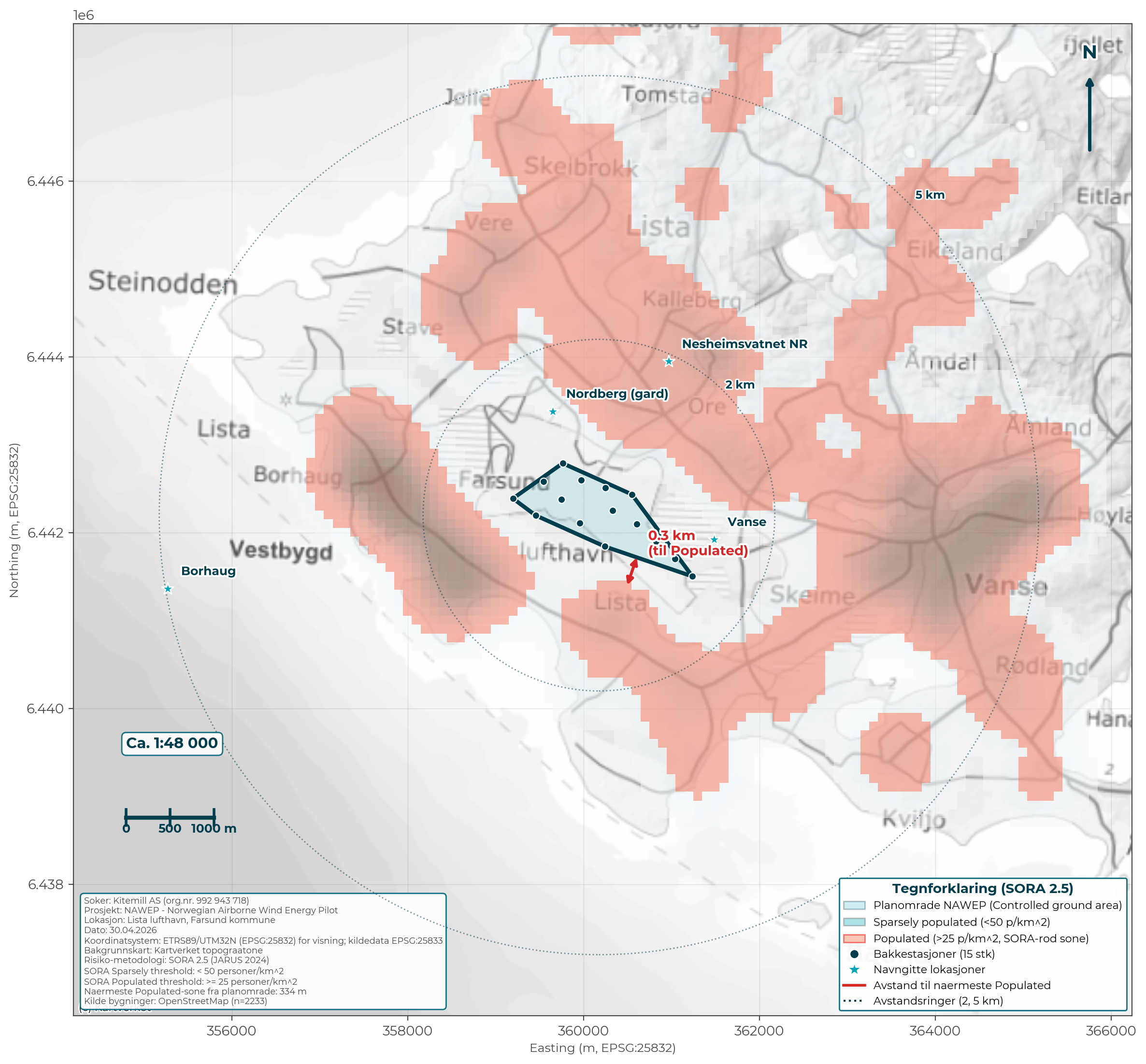 Figure 4.10: SORA classification in accordance with Kitemill's BVLOS approval (NOR-OAT-000294/000). Light blue area: plan area (Controlled ground area). Red semi-transparent overlay: "Populated" zones (> 25 p/km²). Cf. chapter 17.2 for containment architecture.
4.10 Distances from ground stations
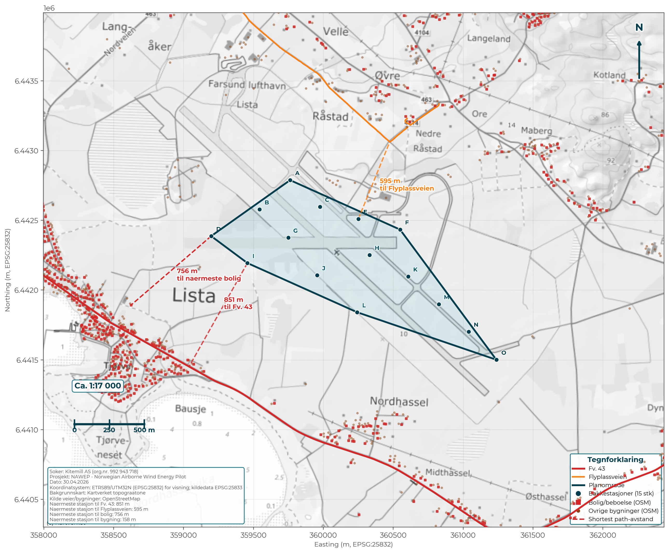 Figure 4.11: Distances from each ground station (A-O) to County road 43 (red), Flyplassveien (orange) and built environment (brown = buildings, red = dwelling). Dashed lines show shortest distance to critical references. Nearest dwelling: 758 m, nearest building: 158 m, nearest county road: 854 m.
A detailed per-station table is included in chapter 7.5 and as Appendix 32.
5. TECHNICAL DESCRIPTION
5.1 AWE technology
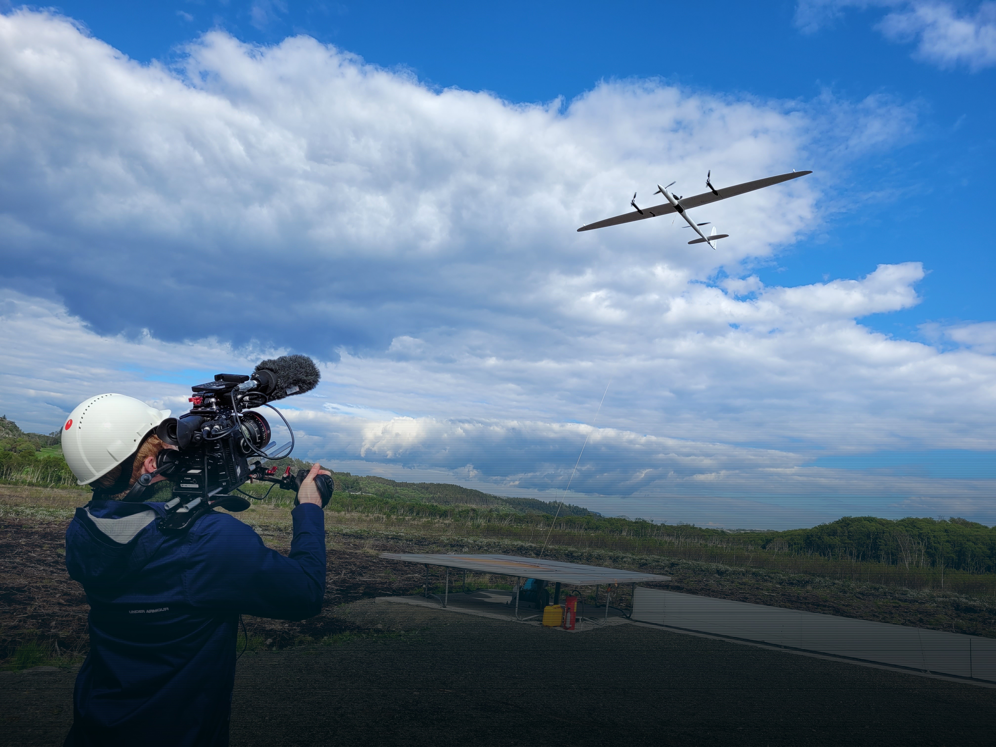
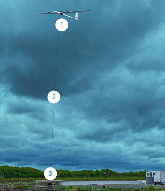 Figure 5.1: Kitemill's AWE system in operation at Lista Airport. (1) Kite - rigid wing with VTOL propellers, (2) Tether - high-strength synthetic line, (3) Ground station with generator, winch and control systems.
Kitemill's system consists of:
1. Kite (wing): Rigid wing with approx. 17 m wingspan
2. Tether: High-strength synthetic line (up to 1,500 m)
3. Ground station: Generator, winch and control systems
5.2 Production cycle
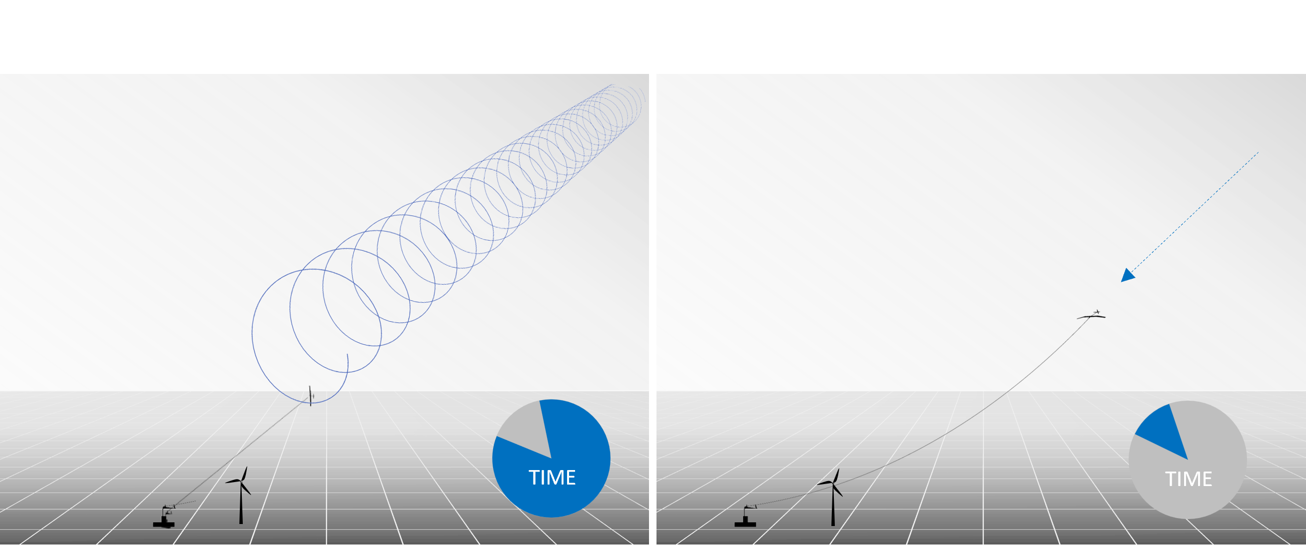 Figure 5.2: The production cycle. Left: Production phase - the kite flies in a circular motion and pulls out the tether while the generator produces electricity (constituting the main part of the cycle time). Right: Return phase - the tether is reeled in with low energy consumption while the kite returns to the starting position.
- Start: The kite is lifted to operating altitude using VTOL propellers (like a drone)
- Production (reel-out): The kite flies in a circular motion and pulls out the tether with great force. The tether force drives the generator on the ground station. This phase constitutes the main part of the cycle time.
- Return (reel-in): The kite is steered to a low-drag position, and the tether is reeled in with low energy consumption.
- Repetition: The cycle is repeated continuously. Net energy production is the difference between the production phase and the return phase.
- Landing: Automatic, in extreme weather or for periodic maintenance.
5.3 System specifications
| Parameter |
Value |
| Capacity per system |
100 kW (average) |
| Number of systems |
15 (12 operational + 3 R&D units) |
| Total installed capacity (grid feed-in) |
1.2 MW |
| Operating wind |
5-25 m/s |
| Kite speed |
Up to 180 km/h (approx. 50 m/s) |
| Operating altitude |
150-500 m above ground |
5.4 Electrical system description (in accordance with the Energy Act Regulations § 3-2)
5.4.1 Generator per kite system (ground station)
| Component |
Specification |
| Type |
Permanent magnet synchronous (PMSG) |
| Rated capacity per unit |
100 kW (average over the production cycle) |
| Rotational speed |
Variable 0-5,000 rpm |
| Drive |
Direct drive on the winch shaft |
| Manufacturer/model |
To be specified in the design phase |
5.4.2 Frequency converter / inverter
The generator delivers variable frequency (depending on the production phase in the kite cycle). The voltage is rectified to DC and inverted to 50 Hz AC for feed-in to the internal grid.
| Component |
Specification |
| Type |
IGBT-based frequency converter (variable frequency → DC → 50 Hz AC) |
| Rated capacity per unit |
150 kW |
| Filtering |
Filtered output to ensure grid quality |
| Grid quality |
In accordance with European and local standards for grid feed-in (EN 50160, IEC 61000 series) |
| Active monitoring |
Continuous monitoring of voltage, frequency, harmonics and power quality; automatic fault handling for values outside the tolerance range |
Internal grid at 690 V AC out of each ground station - no local transformer at the ground stations. The central transformer station at Kitemill's substation (3 oil-filled units of 450 kVA each in parallel, 1,350 kVA total) steps the voltage up to 22 kV before connection to Glitre Nett's grid.
| Component |
Specification |
| Central transformer station (Kitemill, upstream of internal grid) |
3 oil-filled units of 450 kVA each (1,350 kVA total), 690 V AC → 22 kV, dimensioned for 1.2 MW + losses |
| Internal grid out of ground station |
690 V AC (after frequency converter) |
| Glitre's transformer (74013) |
Separate unit, Glitre Nett's responsibility (22 kV / regional voltage) |
5.4.4 Voltage level hierarchy
| Level |
Voltage |
Description |
| Generator |
400 V / 690 V AC (variable frequency) |
Low voltage out of each ground station |
| After frequency converter |
690 V / 50 Hz AC |
To internal transformer |
| Internal grid (Kitemill) |
690 V |
Cable between ground stations and central point |
| Connection point (Glitre) |
22 kV |
At new substation 74013 |
| Regional grid |
110 kV |
Vanse TS |
5.4.5 Metering
- Settlement metering against Glitre: Class 0.5S combined active/reactive metering. Located on Kitemill's side of the interface. Class 0.5S has been chosen because the economics of power delivery is secondary in the pilot project (R&D/knowledge building is the main objective).
- R&D metering per ground station: Each ground station is metered via the grid converter's own metering unit. This provides continuous production data per unit for R&D purposes (not Elhub metering).
- Reactive power regulation: Adapted to the grid company's requirements in accordance with the connection agreement.
5.4.6 Certifications
| Type |
Status |
| CE marking of electrical components |
Established as part of the delivery |
| IEC 61400 series (relevant parts for AWE-adapted use) |
Followed where relevant; specific standard for AWE under preparation in IEC TC 88 |
| EN 50160 / IEC 61000 series (grid quality) |
Followed by frequency converters and control system |
| CAA-N operating permit |
BVLOS NOR-OAT-000294/000 (Appendix 05), VLOS ref. 22-02391-46 (Appendix 04) |
| Operations Manual QP-OPS-001 rev. 4.0 |
CAA-approved (January 2026) |
| Norwegian electrotechnical regulations (FEK, FSE, NEK 400) |
Followed for the entire plant |
6. GRID CONNECTION AND ELECTRICAL INFRASTRUCTURE
6.1 Grid connection principle and interfaces
The grid connection of NAWEP is established through Glitre Nett AS pursuant to the obligation to connect (henteplikten), cf. Energy Act § 3-4. Glitre Nett confirms in a maturity assessment dated 21.11.2024 (ref. IN-00002114, Appendix 03) that the project is assessed as mature, and that connection of feed-in of 1.2 MW is operationally sound in the distribution grid, regional distribution grid and transmission grid.
Division of work and interfaces
- Glitre Nett AS builds, owns and operates: The connection to the existing distribution grid up to and including the transformer at the new substation at Lista Airport. The new substation replaces the existing substation 74013-LISTA FLYSTASJON and is established with two high-voltage metering points - one for NAWEP and one for Solkraft Lista.
- Kitemill AS (developer) builds, owns and operates: All grid from the connection point (outgoing side of Glitre's transformer) and onwards internally to the 15 ground stations, including internal grid, internal transformer/substations and metering equipment on the Kitemill side.
- Ownership boundary: On the secondary side of Glitre's transformer at the new substation.
Cost allocation
Kitemill AS covers the construction contribution (anleggsbidrag) for any grid reinforcements that may be required by the feed-in, cf. the Regulations on economic and technical reporting etc.
6.2 Connection point and voltage level
- Connection point: New substation at the location 74013-LISTA FLYSTASJON at Lista Airport, replacing the existing substation 74013.
- Connection voltage level: 22 kV (distribution grid, supplied from Vanse transformer station 110/22 kV).
- Upstream supply point: Vanse TS (110 kV/22 kV).
6.3 Capacity and operational soundness
Glitre Nett confirms in its maturity assessment (ref. IN-00002114, dated 21.11.2024, cf. Appendix 03):
- Distribution grid: Operationally sound upon construction of the connection point as described in Appendix 1 to the maturity assessment.
- Regional distribution grid: Capacity beneath the transformer at Vanse TS (110/22 kV), and capacity onwards to the nearest transmission grid.
- Transmission grid: As the feed-in is below 5 MW, the project is exempt from Statnett's requirement for an operational soundness assessment at the transmission grid level. The connection is regarded as ordinary supply.
Glitre explicitly confirms that there is capacity for both NAWEP (1.2 MW) and Solkraft Lista (planned in parallel) in the relevant grid. The connection is operationally sound on ordinary terms, and there are no conditions on disconnection or production restrictions for NAWEP.
| Component |
Description |
| New substation (Glitre) |
Replaces existing 74013-LISTA FLYSTASJON, no new land take beyond the existing station area |
| Metering points |
2 high-voltage (Kitemill + Solkraft Lista) |
| Distribution voltage level |
22 kV |
| Kitemill central transformer station |
3 oil-filled units of 450 kVA each (1,350 kVA total), 690 V / 22 kV, dimensioned for 1.2 MW + losses (cf. section 5.4.3) |
| Ground stations |
No local transformer - 690 V AC out directly from frequency converter |
| Transmission voltage level |
110 kV (Vanse TS) |
| Cable routing |
Underground cable in existing and new corridors (total length approx. 5,114 m, cf. tender from external contractor) |
6.5 Internal grid
Grid specifications:
- Total cable length: 5,180 m
- Maximum capacity per unit: 180 kW
- Continuous combined delivery: 1,200 kW
- Units: A-M with individual distances
[See Appendix 17: Grid drawings (Shapefile)]
6.6 Installed capacity and annual production
| Parameter |
Value |
| Installed capacity (grid feed-in) |
1.2 MW |
| Production units |
12 units (stations A-L) |
| R&D units |
3 units (stations M, N, O) - not included in the production calculation |
| Capacity per unit |
100 kW average |
| Expected annual production (mature operation) |
4.2 GWh |
| Full-load hours (mature operation) |
3,500 hours |
Production ramp-up plan:
| Year |
Full-load hours |
Annual production |
| 2027 |
800 hours |
960 MWh |
| 2028 |
1,200 hours |
1,440 MWh |
| 2029 |
2,000 hours |
2,400 MWh |
| 2030+ |
3,500 hours |
4,200 MWh |
Calculations based on PowerSim (version 37), validated against KM1 prototype testing.
[See Appendix 03: Maturity assessment Glitre Nett 21.11.2024]
6.7 Climate benefit and resource efficiency
6.6.1 Greenhouse gas savings
Production of renewable energy displaces fossil-based power production in the European power market. The EU Innovation Fund's GHG calculation methodology uses an emission factor of 0.15 tonnes CO2 equivalents per MWh for the reference grid. Based on this, the project's climate contribution can be estimated:
| Parameter |
Value |
| Emission factor reference grid (EU) |
0.15 tonnes CO2e/MWh |
| Annual production at mature operation |
4,200 MWh |
| Estimated annual CO2 savings at mature operation |
~630 tonnes CO2e |
Production will ramp up gradually in line with technology maturation (cf. section 6.5). In an early phase, actual production and thus climate effect will be lower than at mature operation. The ramp-up plan reflects that this is a new technology where operating experience and adaptation to local conditions will affect the production level.
For comparison, 4,200 MWh corresponds to the electricity consumption of approximately 260 Norwegian households (based on average consumption of 16,000 kWh/year, Statistics Norway).
6.6.2 Resource efficiency
AWE technology differs substantially from conventional wind power in material consumption and land take. Kitemill estimates, based on the company's system design, indicate the following comparisons:
| Parameter |
Conventional wind power |
AWE (Kitemill) |
| Material consumption |
~500 tonnes per MW |
~50 tonnes per MW |
| Ground footprint per unit |
~2,000 m² (foundation, road, hardstanding) |
~36 m² (ground station 6×6 m) |
| Permanent terrain interventions |
Concrete foundation, access roads, hardstandings |
None - movable steel frame |
| Infrastructure |
Special transport, crane operations, access roads |
Standard vehicles, underground cables |
These figures are based on the company's own calculations and will be verified through the NAWEP project. The fundamental material saving follows from the AWE system replacing tower, nacelle and rotor blades with a light wing profile and an anchoring tether. The ground station with generator constitutes the main part of the material consumption.
The low material intensity also gives a shorter Energy Payback Time (EPBT). Faggian et al. (2019) estimate EPBT for AWE systems at approx. 5 months, compared with approx. 9.5 months for conventional wind power. The climate footprint per kWh produced is correspondingly reduced.
6.6.3 Reversibility
A significant property of AWE installations is that they can be removed without lasting traces in the terrain. The ground stations are bolted to the ground without concrete foundations, and internal cable infrastructure is laid as underground cable. Upon project termination, the area can be restored to its original condition without costly demolition works.
6.8 Economy
6.7.1 Investment costs (CAPEX)
All figures are estimates at pilot/demo level (immature technology) and will be adjusted in detailed design. Ordinary market-based uncertainty intervals are included.
| Cost item |
MNOK |
Basis |
| Kite systems (kite + ground station + line + control system), 15 x 3 MNOK |
45.0 |
Kitemill estimate (pilot, immature) |
| Civil works and trenches (stages A+B+C + options) |
3.42 |
Written tender from external contractor, 27.08.2025 (exempt from public access under Public Access Act § 13) |
| Electrical infrastructure (3 x 450 kVA transformer, 22 kV internal grid, cabling - materials, excl. laying) |
8-10 |
Kitemill estimate |
| Construction contribution to Glitre (upgrade of substation 74013) |
2-4 |
Depends on Glitre's final tender |
| SCADA, monitoring and control systems |
3-4 |
Kitemill estimate |
| Engineering, permits, expert assessments |
3-4 |
Kitemill estimate |
| Construction works (electrical assembly, commissioning, testing) |
4-5 |
Kitemill estimate |
| Contingency (~12%) |
8-10 |
Standard practice |
| Total CAPEX (pilot) |
76-85 MNOK |
|
The tender from the external contractor for civil works is costed and is enclosed as Appendix 09 (EXEMPT FROM PUBLIC ACCESS) pursuant to Public Access Act § 13 (trade secrets).
6.7.2 Operating costs (OPEX) per year
| Item |
MNOK/year |
Source |
| Baseline O&M (based on LCOE model KM2 series production) |
~0.8 |
LCOE model (45.5 EUR/kW/year x 1,500 kW) |
| Pilot/R&D supplement: |
|
|
| - Monitoring and operation (R&D operating personnel) |
1.5-2.0 |
Kitemill estimate |
| - Bird monitoring and biological field campaigns |
included |
Annual field campaign in line with mitigation measures (cf. chapter 9) |
| - Grid tariff and feed-in tariff |
0.2-0.4 |
Standard tariff |
| - Insurance |
0.3-0.5 |
Kitemill estimate |
| - Ground rent and administration |
0.3-0.5 |
Kitemill estimate |
| Total OPEX (pilot) |
~3.5-5.0 MNOK/year |
|
The OPEX estimate includes an annual cost item for biological field campaigns and bird monitoring in accordance with the mitigation measures described in chapter 9. The item finances independent professional follow-up of migratory birds and biodiversity throughout the operating phase, and forms part of the licensee's commitment to monitoring and reporting.
6.7.3 Support schemes
| Scheme |
Status |
| EU Innovation Fund (NAWEP) |
Awarded |
| AWE-KM2 grant (Horizon Europe) |
Confirmed |
| SkatteFUNN |
Confirmed |
| Research Council of Norway IPN |
Under application (decision May 2026) |
| Enova |
Application planned - subject to license being granted |
| Guarantees of origin (Norwegian renewable guarantee) |
Registration planned from commissioning |
The project has been awarded EU Innovation Fund support through the NAWEP programme and has secured the AWE-KM2 grant. Supplementary financing is expected through the Research Council of Norway IPN and the SkatteFUNN scheme. Enova support is planned to be applied for after the license has been granted, as Enova's R&D/demo programme requires an established license.
7. LAND USE AND PLANT COMPONENTS
7.1 Ground station
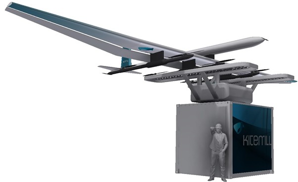
- Size: approx. 6 x 6 metres footprint
- Height: approx. 3 metres
- Foundation: Steel frame, no concrete foundation
- Reversibility: Can be removed without lasting traces
Figure 7.1: Ground station with kite in parked position. The person illustrates the system's scale.
7.2 Service area
- Existing hangars are used
- No new buildings planned
7.3 Land take
The project is designed with minimal permanent land take. The table below shows total direct intervention based on Kitemill specification and a written tender from an external contractor (ref. chapter 6.7).
| Type of intervention |
Permanent (m²) |
Temporary (m²) |
| Ground stations 15 x 25 m² (gravel pad 5 x 5 m per unit) |
375 |
- |
| Civil works area around ground stations (external contractor's assumption: 30 m² per unit) |
- |
450 |
| Cable trench in field (4,556 m x approx. 1 m during construction phase; restored after construction) |
0 |
approx. 4,556 |
| Cable trench in asphalt (72 m) with re-asphalting |
144 |
144 |
| Drilling pits, 9 units |
0 |
approx. 27 |
| Upgrade of existing substation 74013 (Glitre) |
0 |
- |
| Kitemill's internal transformers (integrated in substation 74013) |
0 |
- |
| Rig area, storage and access road |
- |
approx. 2,500 |
| Total |
~520 m² |
~7,700 m² during construction phase |
- Permanent land take: approx. 520 m² (approx. 0.05 ha)
- Temporary construction area: approx. 7,700 m² (approx. 0.77 ha), restored after construction
- Total cable corridor internal grid: 5,114 m (excavation + drilling)
- Glitre Nett: No new land take. The upgrade takes place within the existing substation 74013.
7.4 Construction phase
The construction period is carried out in two phases over a total of approx. 15 months, divided between 3 months in 2027 (installation of 3 R&D systems M, N, O) and approx. 12 months in 2028 (installation of stations A-L, grid connection and commissioning). Continuous on-site construction activity in each phase is approx. 3 and 12 months, respectively. Planned commissioning is 31.12.2028, cf. schedule in chapter 3.4.
The construction phase encompasses the following activities:
- Establishment of gravel pads at up to 15 locations (5 x 5 m per location)
- Installation of internal cabling (underground cable, total approx. 5,114 m)
- Deployment of 15 ground stations
- Upgrade of the existing substation 74013 (Glitre), without new land take
- Transport with ordinary vehicles (lorry, crane truck)
The construction works entail no blasting, spoil deposits or permanent terrain interventions beyond a cable trench in asphalt that is re-asphalted. Noise and vibrations from construction machinery will be limited and of a temporary nature, equivalent to ordinary construction activity. Upon completion, affected areas are restored to their original condition.
7.5 Distances from ground stations to roads and built environment
No ground station is closer than 854 m to county road 43 or 596 m to Flyplassveien. The nearest building in the airport area (including hangars and technical buildings) lies 158 m from the nearest ground station. The nearest dwelling is 758 m from the nearest ground station. All distances are measured as the shortest line in EPSG:25833 (ETRS89/UTM33N), based on actual station locations in the shapefile and road/building data from OpenStreetMap.
A detailed per-station distance table and map are enclosed as Appendix 32 - Distance calculations.
8. BIODIVERSITY
8.1 Area description
The Lista area has recognised natural values and includes:
- Ramsar status (international wetland protection since 1996)
- 1.3 million bird observations in the Norwegian Species Database (Artsdatabanken)
- 34 red-listed bird species documented in the area
8.2 Protected areas
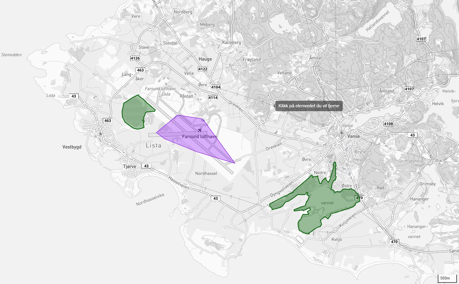 Figure 8.1: Operating area (purple) in relation to the nearest nature reserves: Slevdalsvannet (west, green) and Nesheimsvatnet (south-east, green). Both form part of the Lista wetland system (Ramsar).
| Protected area |
Type |
Distance |
| Slevdalsvannet nature reserve |
Nature reserve |
approx. 330 m west |
| Lista wetland system |
Ramsar |
Adjacent |
| Lista beaches |
Landscape protection area |
approx. 500 m |
8.3 Habitat types
The plan area mainly comprises airport areas and cultivated land. No threatened habitat types are registered within the plan area.
In adjacent areas, the following are registered:
- Oceanic raised bog (NiN), associated with the habitat type Atlantic raised bog
- Salt marshes
- Coastal heath
These are not affected by the project.
8.4 Red-listed species
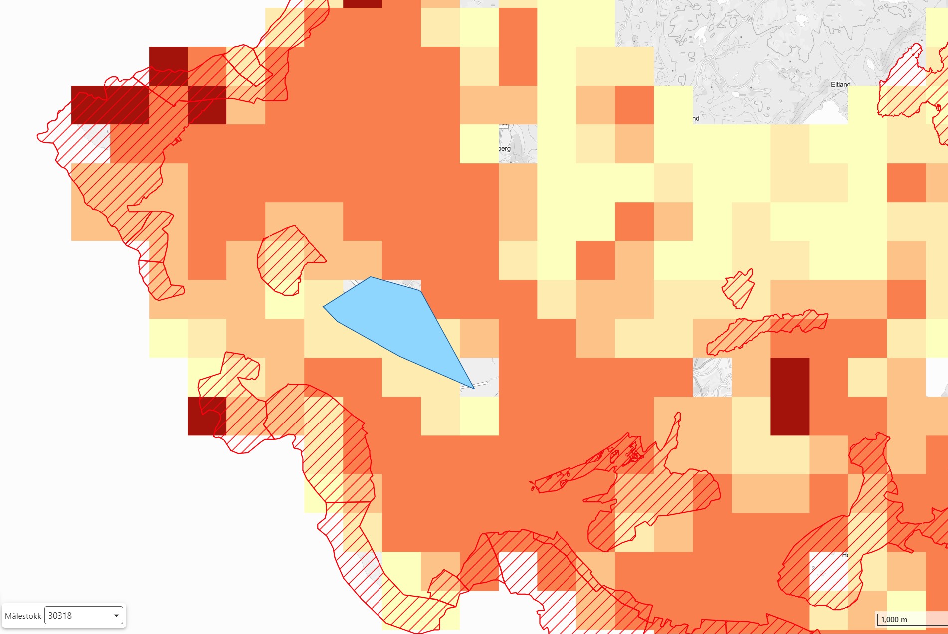 Figure 8.2: Operating area (blue) shown with protected areas (red hatched areas) and species records from the Norwegian Species Database (colour intensity indicates registration density). Most records in the area are linked to birds. The project area lies in an area of moderate registration density compared with surrounding nature protection areas.
Based on the Norwegian Species Database, rare coastal plants are registered in surrounding areas, including sea holly and soft mermaid grass. The species are associated with coastal stretches outside the plan area.
8.5 Assessment
The plan area is already heavily affected by human activity. The AWE plant will have limited direct impact on habitat types since:
- No new roads are built
- Minimal interventions in the ground
- Operation takes place in the airspace
9. BIRDS AND MIGRATORY BIRDS
This assessment has been prepared in cooperation with Arnold Håland, NNI Resources AS, based on NNI Report 520 (2018) and updated assessment (2024).
9.1 Summary
Lista is a recognised bird locality. The applicant has prepared a comprehensive plan for mitigation measures and monitoring in accordance with the Nature Diversity Act §§ 8-12.
9.2 Relevant species
The following species have been specifically considered in the monitoring programme:
1. Marsh harrier
2. Common crane
3. Lesser black-backed gull
4. Common swift
5. Barn swallow
6. Skylark
7. Meadow pipit
9.3 Knowledge base
Existing knowledge:
- NNI Report 520 (2018), commissioned by Kitemill: 110 hours of fieldwork
- Norwegian Species Database: 1.3 million observations
- Updated assessment by Arnold Håland (2024)
Knowledge building:
Existing surveys of the bird life at Lista are extensive. The project will further strengthen the knowledge base in the following areas:
- Spring migration: Surveying of the spring migration will supplement existing data on the autumn migration.
- Altitude distribution: Systematic recording of birds' flight altitudes in the plan area through the seasons.
- AWE-specific response: Documentation of bird behaviour in the vicinity of AWE systems, contributing to the knowledge base for this new technology.
This knowledge building forms a central part of the project's monitoring programme, cf. Nature Diversity Act § 8.
9.4 Assessment of scaling from 1 to 15 systems
Arnold Håland (NNI) has, in an updated assessment (November 2024), assessed the consequences of scaling from a single test unit to 15 simultaneous systems (12 production units + 3 R&D units). Main findings:
- Collision risk increases proportionally with the number of systems in operation, estimated at a minimum of 15 times the level observed in the 2018 study. The three R&D units (M, N, O) are operated primarily under observation and with reduced operating windows (daytime operation, shutdown during migration periods), so that the overall collision risk is based on 12 production systems in full operation plus 3 R&D systems with limited operating time.
- Both visual and acoustic impact on birds increases, and birds have to perform more complex avoidance behaviour.
- A natural mitigating factor exists: strong wind correlates with lower bird activity in the airspace, which reduces the overlap between operation and bird exposure.
- Skylark is identified as a vulnerable species, with breeding pairs on hangars in the area.
- Movement patterns along the southern side of the airport (west-east corridor) and the airspace towards Slevdalsvannet require particular attention.
- The October migration represents a period of high bird activity. Spring migration has not yet been studied. These knowledge gaps form part of the rationale for the R&D project.
Breeding birds: In addition to migratory birds, Lista is an important breeding area for several species. Among the species listed in 9.2, skylark and meadow pipit breed in the cultural landscape around the plan area, and the open agricultural landscape on Lista also hosts other waders (lapwing, curlew, oystercatcher) that are sensitive to disturbance during the breeding season (April-July). Professional assessment of impact on breeding birds is part of Håland's updated assessment (2024) and is included in the monitoring programme (chapter 9.7) through dedicated breeding-season campaigns. The breeding season is treated as an operationally sensitive period on a par with migration periods in the mitigation measures (chapter 9.6).
9.5 Phased ramp-up and risk management
To uphold the precautionary principle (Nature Diversity Act § 9), the project is structured with a gradual ramp-up where operation is adapted based on accumulated knowledge:
| Year |
Activity |
Bird-related measures |
| 2026 |
1 system, daytime flying only |
Negligible burden. Monitoring programme established (field campaigns spring/summer/autumn) |
| 2027 |
Up to 4 systems (stations K, M, N, O) |
Daytime and some night-time flying under observation. Focus on spring and autumn migration periods |
| 2028 |
12 systems |
Operational shutdown in the most active migration period |
| 2029 |
Partial operation with observation |
Evaluation of impact based on data from 2028. Adaptation of operating pattern |
| 2030 |
Full operation |
Subject to the impact being assessed as acceptable in 2029 |
Most bird migration takes place at night. The most effective mitigation measure is operational shutdown during periods of high migration activity. In the event of unacceptable consequences, the plan can be adjusted or reversed.
The approach has been developed in dialogue with NNI Resources AS and is based on the knowledge base from the 2018 study and Håland's updated assessment (2024). Kitemill commits to sharing all collected data with the County Governor and NVE throughout the project period.
9.6 Mitigation measures
- Gradual ramp-up over 5 years
- Daytime flying only in 2026
- Operational shutdown / restriction during the busiest migration periods (from 2028) and during the vulnerable breeding season (April-July) where monitoring documents the need
- Bird monitoring through field campaigns (spring, breeding season, autumn)
9.7 Field plan 2026 and subsequent years
| Period |
Number of sessions |
Focus |
| Spring (April-May) |
2 |
Spring migration and early breeding |
| Breeding season (May-July) |
2 |
Breeding birds — skylark, meadow pipit, lapwing, curlew, oystercatcher and other waders |
| Autumn (Sept-Oct) |
2 |
Autumn migration |
10. LANDSCAPE AND VISUAL IMPACTS
10.1 Landscape character
The Lista peninsula is characterised by:
- Flat, open coastal landscape
- Agricultural landscape with stone walls
- Historic airport profile
- Exposed to the North Sea
10.2 Visual impact
| Aspect |
Assessment |
| Visibility |
Kites visible on a clear day up to 3-5 km |
| Movement |
Dynamic, circular motion |
| Light marking and obstruction lights |
See section 10.2.1 |
| Reversibility |
Fully reversible, no permanent structures at altitude |
10.2.1 Light marking and visual marking
Marking of aviation obstructions is regulated by regulation BSL E 2-1 (FOR-2014-07-11-980). The regulation was updated in 2023-2024 and, under § 13 third paragraph, expressly covers anchored unmanned aircraft, which is the definition that covers Kitemill's kite system.
Basic requirements under BSL E 2-1 § 13 (3):
| Height above ground |
Colour marking of tether |
Light at the top |
| 60-100 m |
Required |
Low-intensity light |
| 100-150 m |
Required |
Medium-intensity light |
| Above 150 m |
Required |
High-intensity light |
NAWEP operates in the altitude range 150-500 m, and would thus, on a direct reading of the regulation, fall under the category "above 150 m".
CAA-N published in 2023 an updated guidance to BSL E 2-1. The guidance to § 13 third paragraph reads (quote):
"An object can be defined as both an aviation obstruction and an aircraft and thus be required to comply with the requirements of both regulations, where AIC-N 15/23 13 OCT provides an explanation. The use of unmanned aircraft above 120 metres is subject to application, and appropriate marking is addressed through SORA, taking the regulation on marking of aviation obstructions as a starting point in so far as this is practicable and does not defeat the purpose of the activity or operation to be conducted. Assessments will, for example, be made when applying for research and development work."
NAWEP satisfies both regulatory regimes:
- SORA regime (the aircraft): Kitemill has operating permits for operation in the specific category under EU Regulation 2019/947 - VLOS KM1 (ref. 22/02391-46) and BVLOS KM1 (NOR-OAT-000294/000, ref. 22/02391-68), cf. Appendices 04 and 05.
- Obstruction regime (the aviation obstruction): Kitemill complies with the reporting and registration obligations under BSL E 2-1 by reporting the kite system as an aviation obstruction to Kartverket's register for aviation obstructions (NRL).
For the actual marking design (tether, kite, light), CAA-N exercises discretion under BSL E 2-1 § 7 (3) and § 21 (2), combined with the R&D clause in the guidance to § 13 (3). This gives CAA-N authority to adapt the marking requirements to NAWEP's operating pattern and research purpose. The regulatory framework is publicly documented through: (i) AIC-N 15/23 13 OCT (CAA-N's circular explaining BSL E 2-1 § 13 in combination with the R&D clause, quoted above), (ii) BSL A 7-2 (Norwegian Regulation 2024-11-01-2777 on unmanned aviation) implementing EU 2019/947, and (iii) Farsund municipality's public case archive 25/00659-5 (cf. Appendix 06) which contains CAA-N's consultation response in full. Kitemill has ongoing dialogue with CAA-N's section for unmanned aviation regarding these matters.
10.3 Visualisations
The following visualisations show the AWE system in operation at Lista Airport. The images have been generated with 3D modelling based on actual station locations and operating altitudes.
Methodology for photo viewpoints: The visualisations from ground level (Figures 10.5 and 10.6) have been produced from Ore krysset (EUREF89 UTM-33: E 8,006.80 / N 6,471,450.86), the nearest publicly accessible viewpoint with unobstructed view towards the project area, and represent the actual visual impression a member of the public will have of the plant. The 3D oblique projections from a bird's-eye perspective (Figures 10.3 and 10.4) are only intended as technical overview maps to illustrate the operating pattern in plan view; they are not assessments of visual impact from publicly accessible viewpoints. Actual photographs of the existing KM1 prototype in operation (Figure 10.7) supplement the documentation of a kite in the air, with explicit reservation that the prototype's location deviates from the planned NAWEP stations.
10.3.1 Overview images - station locations
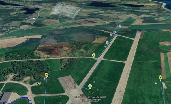 Figure 10.1: 3D view from the south (oblique perspective) showing selected station locations (F, H, K, M, N, L) along the runway. The lines illustrate connections between stations and operating areas.
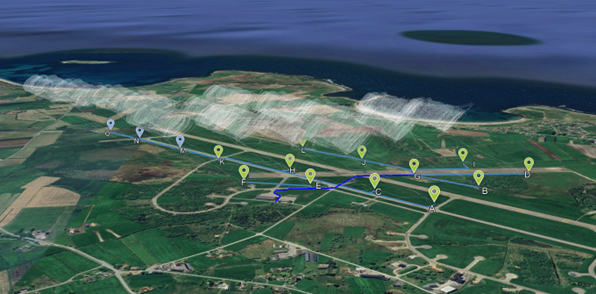 Figure 10.2: Overview of all 15 stations (A-O) with visualised circular movements for the kites in operation. Seen from the south-east (oblique perspective) with the sea in the background.
10.3.2 Technical overview maps - operating pattern in plan view
Note: The figures below are 3D renderings from a bird's-eye perspective and are only technical overview maps. They are not intended as assessments of visual impact from publicly accessible viewpoints - for that, refer to Figures 10.5 and 10.6 (seen from Ore krysset).
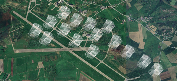 Figure 10.3: 3D rendering from above (technical overview map, bird's-eye perspective) showing the operating circles of all 15 systems in plan view. Each cylinder represents the area in which one kite operates in circular motion. Not a publicly accessible viewpoint.
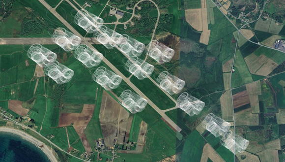 Figure 10.4: 3D rendering, alternative oblique angle from above (technical overview map) showing the operating pattern in relation to the runways and surrounding landscape. Not a publicly accessible viewpoint.
10.3.3 Visualisation seen from a publicly accessible viewpoint (Ore krysset)
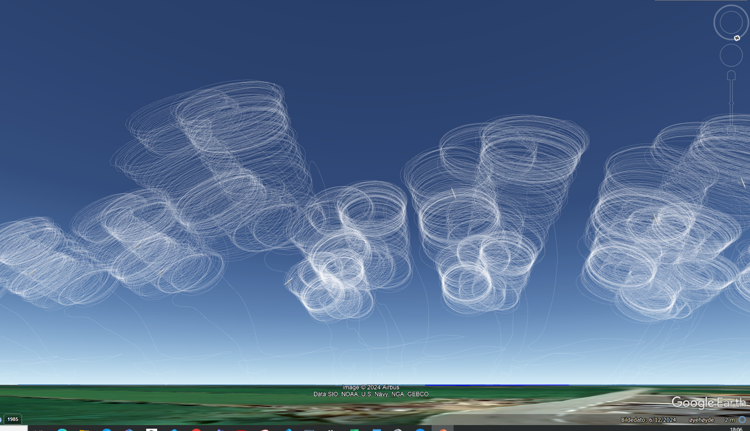 Figure 10.5: Visualisation seen from Ore krysset (public road, nearest accessible viewpoint towards the project area; EUREF89 UTM-33: E 8,006.80 / N 6,471,450.86) showing the kites' circular motions against the sky. Operating altitude 200-400 m above ground.
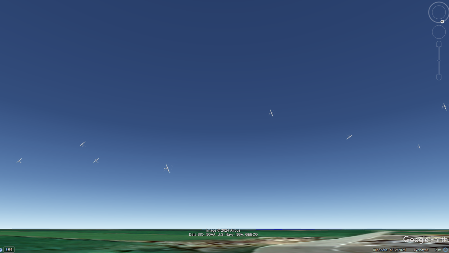 Figure 10.6: Visualisation seen from Ore krysset (EUREF89 UTM-33: E 8,006.80 / N 6,471,450.86) showing all 15 kites in operation. The kites (17 m wingspan) are visible as small objects against the sky at typical operating altitude.
10.3.4 Actual photo - existing KM1 prototype at Lista
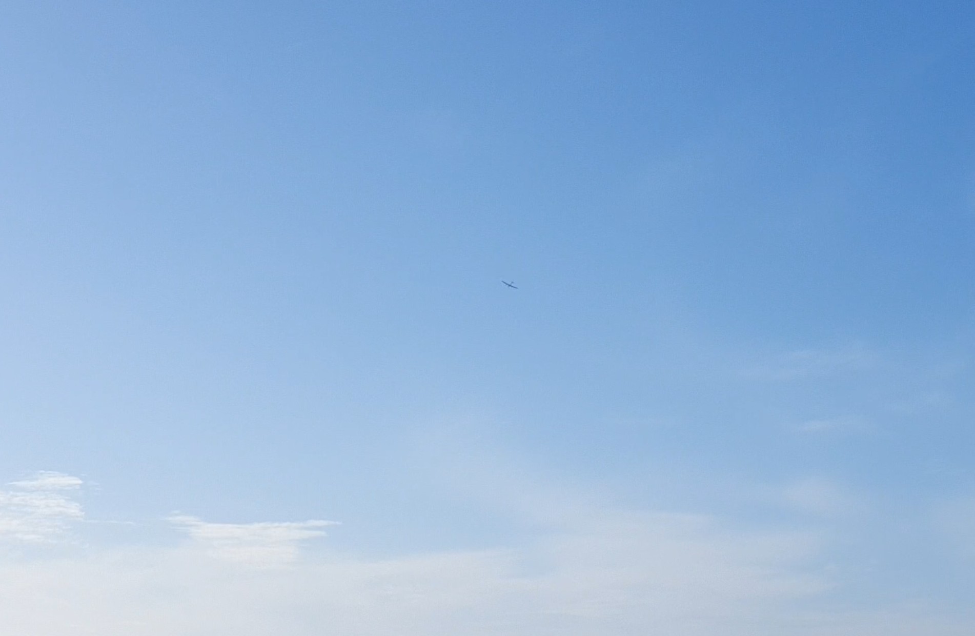 Figure 10.7: Photo from actual flight with Kitemill's existing KM1 prototype at Lista Airport. Reservation: The KM1 prototype is at a different location from the planned NAWEP stations (A-O) and is shown here only to document the actual visibility of a kite in operation against the sky. The kite does not cover the solar disc from normal operating altitude, and shadow flicker has not been observed.
10.3.5 Methodology
The visualisations have been prepared with the following methodology:
- Background images: Satellite imagery and 3D terrain model from publicly available sources
- Station locations: Based on actual coordinates from the planned grid layout
- Operating circles: Visualised as cylindrical volumes with radius corresponding to tether length
- Scale: The kites are presented at actual size (17 m wingspan) relative to the surroundings
Assessment of visual impact:
- The kites are visible as small objects against the sky at distances above 500 m
- No permanent structures above ground level beyond ground stations (approx. 3 m height)
- Dynamic movement (circles) differs from static wind turbines
- Visual impact is assessed as moderate. The smaller physical dimensions of AWE systems and the absence of permanent structures at altitude give a different visual character from conventional wind power
11. ACOUSTICS
11.1 Knowledge base
The knowledge base for the acoustic assessment is based on the following sources:
-
Inge Hommedal (2016): Early study for Kitemill conducted by an engineer with a background from Kjelde akustikk AS and SWECO.
-
Bouman, N. (2023): Acoustic field measurements of Kitemill's KM1 system carried out at Lista Airport, March 2023. MSc thesis, Delft University of Technology. Available: https://repository.tudelft.nl/record/uuid:390a153c-0114-44c8-8b43-d9efc3e8cdd1
-
T-1442/2021: The Norwegian guideline for the treatment of noise in land-use planning is used as the basis for threshold values.
The plan area lies within an existing noise zone from air traffic, mapped by Sweco (2020) as part of the airport's sequence provisions. The acoustic contribution from the AWE plant comes in addition to this existing burden.
11.2 Sound sources during AWE operation
The AWE system's sound sources are fundamentally different from conventional wind power:
| Sound source |
Operating phase |
Character |
| Tether vibrations |
Production (main source) |
Tonal, whistling sound |
| Aerodynamic wing noise |
Production |
Broadband |
| VTOL propeller |
Take-off/landing |
Low-frequency (~100 Hz) |
| Generator/winch |
Continuous |
Low level |
11.3 Measured values from Lista (Bouman 2023)
Acoustic field measurements of Kitemill's KM1 test system were carried out at Lista on 27 March 2023 with class 1 instrumentation (Brüel & Kjær 4189 microphone, B&K 2250 sound level meter, calibrated 114 dB/1000 Hz). The measurements are documented in Bouman, N. (2023) Aeroacoustics of Airborne Wind Energy Systems, MSc thesis at TU Delft.
11.3.1 Measurement set-up and geometry
| Parameter |
Value |
| Test date |
27 March 2023 |
| Test system |
Kitemill 30 kW test system |
| Ground wind (measurement) |
9.1 m/s from NW |
| Kite speed |
0-40 m/s |
| Kite flight altitude above ground (z) |
150-350 m |
| Horizontal distance kite-microphone (d) |
600-1,100 m |
| Slant range microphone-kite (r = √(d² + z²)) |
620-1,150 m |
| Microphone location |
~3 m from winch at ground level |
11.3.2 Measured noise levels
| Parameter |
Value at microphone |
| OASPL (Z-weighted) production phase |
~75-90 dB |
| OASPL(A) production phase |
~65-75 dB(A) |
| OASPL(A) start-up phase |
~75-90 dB(A) (higher due to low-frequency content) |
| Dominant peak frequencies |
1,500 Hz and 2,000 Hz |
| Secondary frequencies |
20 Hz (constant), 180 Hz (low speed), 300-500 Hz (broadband) |
Important note on source decomposition: The microphone was located ~3 m from the winch and simultaneously 620-1,150 m (slant range) from the kite. The measured OASPL(A) is a combined measurement of:
- Winch noise from the ground station (close to the microphone)
- Kite noise from a slant range of 620-1,150 m
Bouman does not separate these two contributions physically. For NAWEP propagation calculation, they are therefore treated as two separate point sources.
11.3.3 Established scaling laws
- Distance: SPL scales with 1/r² (6 dB reduction per doubling of slant range, spherical spreading)
- Kite speed: SPL scales with v^4.5 (typical for broadband trailing-edge noise)
11.4 Assessment of noise at the nearest settlement
Note: Illustrative analysis
The calculations and scenarios presented in this chapter are an example based on KM1 test data (Bouman 2023, 30 kW) scaled to KM2 size (100 kW). The KM2 system is still under development, and noise is one of the design parameters being optimised through the project's development phase. Kitemill is actively working on trailing-edge design, tether design and operational algorithms to minimise noise at the production system. Based on this work, Kitemill expects the KM2 plant to lie within recommended threshold values (T-1442/2021 Lden 45 dB(A) at noise-sensitive built environment).
The analysis in section 11.4 illustrates calculation methodology and operational scope, and provides a basis for the mitigation measures and commitments in section 11.7. Final documentation of actual noise levels takes place through the measurement programme after commissioning of the first KM2 system (cf. section 11.7.3).
For a correct geometric calculation, we distinguish between the two sources and use slant range (3D distance) from the kite to the receiver, not only horizontal distance. The ground station is treated separately as a point source at ground level.
11.4.1 Geometric model
Each of the 15 NAWEP units has two sound sources:
- Ground station (winch): Point source at (x_s, y_s, 0). Horizontal distance d_horiz to receiver.
- Kite in the air: Moving source within an operating volume around the ground station. Tether length 400-800 m, altitude 150-500 m AGL. The kite can in principle be anywhere in this hemisphere.
Slant range from kite to receiver: r_i = √(d² + h²) where d is horizontal distance from kite and h is altitude.
The sound pressure level at the receiver from one source i (spherical spreading, free field):
Lp_i = Lw_i - 20·log10(r_i) - 8
where Lw_i is the source's sound power level and r_i is the distance from source i to the receiver. The distance enters explicitly into each Lp_i.
When multiple independent sources contribute simultaneously, the sound pressure levels are summed logarithmically (energetically):
Lp(receiver) = 10·log10(Σ 10^(Lp_i / 10))
Combined formula in which the distance is visible:
Lp(receiver) = 10·log10(Σ 10^[(Lw_i - 20·log10(r_i) - 8) / 10])
Each of the 30 sources (15 ground stations + 15 kites) has its own distance r_i to the receiver, and thus its own contribution Lp_i. The nearest source dominates; halving the distance gives +6 dB in contribution from that source.
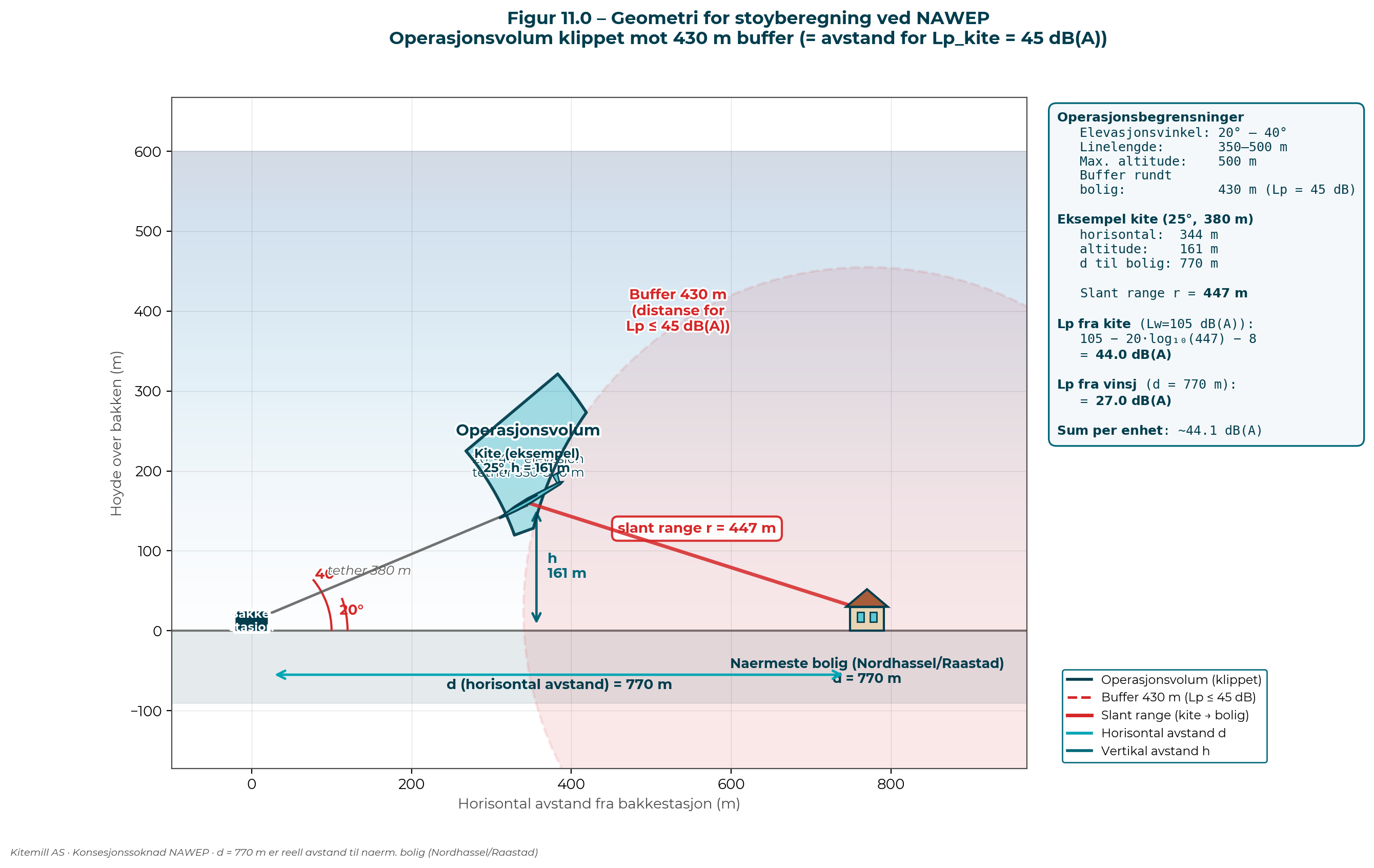 Figure 11.0: Geometry for noise calculation at NAWEP. The operating volume (cyan) is clipped against a 430 m buffer around the nearest dwelling (Nordhassel/Råstad, d = 770 m). The buffer is physically anchored: at slant range 430 m, one kite gives Lp = 105 - 20·log10(430) - 8 = 44.3 dB(A) - just below the T-1442/2021 threshold value 45 dB(A). Example: kite at 25° elevation, 380 m tether, h = 161 m. Slant range to dwelling 447 m, Lp_kite = 44.0 dB(A); winch contributes 27.0 dB(A); sum per unit ≈ 44.1 dB(A). The buffer ensures per-kite compliance; for cumulative Lden ≤ 45 dB(A) from all 15 stations, additional mitigation measures are required (section 11.7).
11.4.2 Sound power levels for KM2 (scaled from Bouman)
Based on decomposition and scaling from the 30 kW test system to 100 kW KM2:
| Source |
Lw scaled to KM2 |
Justification |
| Kite (KM2, 100 kW) |
~105 dB(A) |
Bouman data + scaling 10·log10(100/30) = +5.2 dB |
| Winch/ground station (KM2) |
~92.7 dB(A) |
Typical for electromechanical winch 100 kW + scaling |
11.4.3 Calculated noise levels at the nearest noise-sensitive settlement (~770 m from the nearest ground station)
The dwelling closest to a ground station lies in Nordhassel (south of the runway, approx. 767 m from station N) and Råstad (north/north-east of the runway, approx. 776 m from station F). These two hamlets represent the dimensioning receiver points for the noise assessment. The calculations below are made for 770 m horizontal distance.
Two scenarios are presented:
Scenario A - Realistic operation (kite at h = 300 m AGL above the ground station):
| Contribution |
Lp at Nordhassel/Råstad (770 m horizontal) |
| Kite at (sx, sy, 300 m), slant range = √(770² + 300²) = 826 m |
105 - 20·log10(826) - 8 = 38.7 dB(A) |
| Winch at (sx, sy, 0), distance = 770 m |
92.7 - 20·log10(770) - 8 = 27.0 dB(A) |
| Sum from one unit |
~38.9 dB(A) |
| Sum from 15 units (realistic geometry) |
~43-47 dB(A) worst case |
Scenario B - Worst case (kite at h = 150 m AGL, lowest permitted production altitude):
| Contribution |
Lp at Nordhassel/Råstad (770 m horizontal) |
| Kite at (sx, sy, 150 m), slant range = √(770² + 150²) = 784 m |
105 - 20·log10(784) - 8 = 39.1 dB(A) |
| Winch |
27.0 dB(A) |
| Sum from one unit |
~39.2 dB(A) |
| Sum from 15 units |
~44-48 dB(A) worst case |
Lden assessment: The plant must be able to operate around the clock (wind-dependent production). Lden = Lp_max without daytime advantage. The calculations above (38.7-39.1 dB per kite alone; 43-48 dB sum from 15 units) are therefore directly comparable with the T-1442/2021 threshold value Lden 45 dB(A). Per-kite Lp is safely below the threshold; the sum from 15 units lies at the outer margin and requires mitigation measures (section 11.7) for robust margin.
11.4.4 Hypothetical worst case: kite directly above settlements
In a purely geometric worst case where the kite is flown at the lowest permitted altitude (150 m) directly above a dwelling in Nordhassel or Råstad, one kite alone gives:
Lp = 105 - 20·log10(150) - 8 = 53.5 dB(A)
This would exceed the threshold value. Such flying is excluded through buffer restriction and operational measures (section 11.7), including geo-fence and restrictions in the Operations Manual that prevent flying closer than 430 m from a dwelling.
11.4.4a Buffer conclusion: 430 m per-kite buffer
The correct buffer around noise-sensitive settlements is physically anchored in the T-1442/2021 threshold value:
Per-kite buffer = 430 m (giving Lp = 105 - 20·log10(430) - 8 = 44.3 dB(A) from a single kite, just below 45 dB(A)). This is the minimum slant range from each kite to the nearest dwelling.
| Distance r |
Lp one kite |
Assessment |
| 300 m |
47.5 dB(A) |
Above threshold - insufficient |
| 398 m |
45.0 dB(A) |
Exact threshold value |
| 430 m |
44.3 dB(A) |
Selected buffer - 0.7 dB margin |
Cumulative Lden from 15 stations also requires mitigation measures. The per-kite buffer alone does not solve accumulation: with all 15 stations in operation and the nearest kite at 430 m from a dwelling, the summed Lp is calculated to be approx. 47-48 dB(A). As NAWEP must be able to operate around the clock (wind-dependent production, no daytime restriction), Lden = Lp without favourable correction. The sum from 15 stations at 430 m nearest kite therefore lies 2-3 dB above the threshold value.
To ensure Lden ≤ 45 dB(A) at the nearest dwelling, a combination of measures is therefore required (section 11.7):
- 430 m per-kite buffer ensures that no individual kite gives Lp > 45 dB(A)
- Bouman measures (BL tripping, helical strake tether, TE optimisation) reduce Lw_kite by -10 to -15 dB - this alone brings cumulative Lden below 45 dB(A) at the dwelling
- Selective operational shutdown of the nearest stations during critical wind direction reduces effective N
- Reduced number of simultaneous systems under specific conditions gives an immediate -2 to -5 dB
The final Lden value at settlements is verified and documented through the measurement programme (section 11.7.4); operation is iteratively adjusted so that the threshold value is observed under actual conditions.
11.4.5 Noise zone map - per station and aggregated
The calculation models the kite envelope (30° elevation, tether 350-400 m) and logarithmic summation of noise from all 15 units. The sound source is the kite in the air, not the ground station - for each receiver point, the kite is placed on the geofence boundary (400 m sphere from ground station, minimum elevation 30°/h_min ≈ 175 m) closest to the receiver, and the slant distance from kite to receiver is used in the sound propagation. The winch, which is actually on the ground, is calculated from the ground station's position (Lw = 92.7 dB(A)).
Figure 11.1: Noise zone map NAWEP - operating scenario with mitigation. Assumptions: KM2 designed for low noise (Lw_kite = 95 dB(A), Bouman measures -10 dB), 12 active stations during the night period (M, N, O marked with open red circles are night shutdown 23:00-07:00 cf. license commitment). Dashed circles show per-station kite envelope (geofence projection, ~360 m) - the horizontal range of the kite at minimum operating altitude, not an actual Lden 45 dB contour. A single KM2 kite produces a maximum of approx. 42 dB(A) at ground (directly below, h_min = 175 m, slant_min = 175 m → Lp = 95 - 20·log(175) - 8 = 42.1 dB), so the threshold value Lden 45 dB(A) can only be exceeded by the logarithmic sum of multiple stations. Filled contours show summed Lden, and the strong red line is the summed Lden 45 dB(A) (T-1442/2021 threshold value). Dwellings in Nordhassel and Råstad lie clearly outside the 45 dB contour. This is the expected operating picture under the license conditions.
11.4.5a Logarithmic summation - why 15 stations give more than one
Sound from multiple independent sources is summed logarithmically (energetically):
Lp_total = 10·log10(Σ 10^(Lp_i / 10))
where Lp_i = Lw_i - 20·log10(r_i) - 8 for each source i. The distance r_i from each individual source enters explicitly into the individual Lp_i. The formula thus says: calculate each contribution based on its own distance, then sum energetically.
Case A - all sources equally far away (same r):
If all sources are equally far from the receiver and have the same Lw, the contribution from each source is equal and the sum becomes 10·log10(N) above one source:
| Number of sources |
Addition above one source (equal distances) |
| 1 |
0 dB (reference) |
| 2 |
+3 dB |
| 4 |
+6 dB |
| 10 |
+10 dB |
| 15 |
+11.8 dB |
Case B - sources at different distances (NAWEP reality):
In NAWEP, distance to receiver varies considerably from station to station. For a Nordhassel dwelling, the nearest station is approx. 765 m away while the furthest is ~1,700 m. The contributions from distant stations are substantially smaller than from the nearest:
| Distance r |
Lp from one kite (Lw=105) |
Contribution in sum (relative to nearest) |
| 765 m |
39.3 dB |
1.00 (reference) |
| 1,000 m |
37.0 dB |
0.59 |
| 1,500 m |
33.5 dB |
0.26 |
| 2,000 m |
31.0 dB |
0.15 |
The sum of 15 stations at Nordhassel (actual distances) gives only ~+8 to +9 dB above the nearest individual contribution - not +11.8 dB. This is because the nearest station dominates the sum and distant stations contribute little.
Practical consequence for NAWEP:
- Per-station kite envelope: approx. 360 m horizontal geofence projection from the ground station. This is NOT a noise contour - one KM2 kite gives a maximum of ~42 dB(A) at the ground (h_min = 175 m, slant_min = 175 m, Lw_kite = 95 dB), so Lden 45 dB(A) is never exceeded by a single station.
- Summed Lden 45 dB(A) contour: only the logarithmic sum of multiple stations can exceed the threshold value. The contour in Figure 11.1 therefore extends beyond the per-station envelopes.
- Nearest station dominates: Shutting down the nearest station gives a 3-5 dB reduction; shutting down a distant station gives <1 dB. Therefore, selective operational shutdown of M, N, O (section 11.7.1 step 3) is effective.
This means that mitigation measures must be considered both for the nearest stations (largest contribution) and for the entire plant (cumulative effect). Bouman measures (section 11.7.1 step 1) reduce Lw_i for ALL stations and are the most effective single measure.
11.4.5b Realistic operating scenarios at Nordhassel and Råstad
Based on actual station distances to the nearest dwellings in Nordhassel (58.089°N, 6.635°E) and Råstad (58.108°N, 6.635°E), operating scenarios have been calculated taking into account wind direction and operating strategy (section 11.7.1 step 3).
Assumptions:
- Lw_kite = 105 dB(A) baseline (KM1 prototype, without noise-reducing measures)
- Per-kite buffer 430 m geo-fence
- Kite at minimum permitted position (kite envelope towards dwelling, clipped by 430 m buffer)
- 24-hour operation, no Lden advantage
- Lp contribution from each station based on actual distance to dwelling
Contribution from each station (baseline Lw=105, clipped to 430 m buffer):
| Station |
Lp at Nordhassel |
Lp at Råstad |
| A |
33.2 dB |
41.2 dB |
| B |
33.6 dB |
37.9 dB |
| C |
34.8 dB |
42.2 dB |
| D |
33.1 dB |
34.8 dB |
| E |
36.0 dB |
43.7 dB |
| F |
36.9 dB |
43.7 dB |
| G |
35.5 dB |
38.3 dB |
| H |
38.4 dB |
40.6 dB |
| I |
35.1 dB |
35.5 dB |
| J |
38.3 dB |
37.6 dB |
| K |
40.4 dB |
39.3 dB |
| L |
42.9 dB |
36.4 dB |
| M |
42.7 dB |
37.2 dB |
| N |
43.7 dB |
35.3 dB |
| O |
43.7 dB |
33.7 dB |
(Stations in bold are buffer-limited to 430 m from the relevant dwelling.)
Logarithmic sum of contributions:
| Scenario |
Lp Nordhassel |
Lp Råstad |
| 15 active (full daytime operation, baseline Lw=105) |
51.3 dB |
51.4 dB |
| 12 active (M, N, O off - night period) |
48.4 dB |
51.0 dB |
| 12 active + nearest-to-Nordhassel off (L) at northerly wind |
47.0 dB |
- |
| 12 active + nearest-to-Råstad off (E) at southerly wind |
- |
50.1 dB |
Even with night shutdown of M, N, O and selective shutdown of the nearest station at critical wind direction, Lp without Bouman measures still lies 2-5 dB above the threshold value 45 dB(A). This is due to several stations in the same distance group (~770-1100 m) each contributing significantly.
With KM2 designed for low noise (Bouman measures, Lw_kite = 95 dB, -10 dB):
| Scenario |
Lp Nordhassel |
Lp Råstad |
| 15 active |
41.3 dB |
41.4 dB |
| 12 active (M, N, O off) |
38.4 dB |
41.0 dB |
| 12 active + nearest off (L or E respectively) at critical wind direction |
37.0 dB |
40.1 dB |
With KM2 fully optimised (Lw_kite = 90 dB, -15 dB - Kitemill's target):
| Scenario |
Lp Nordhassel |
Lp Råstad |
| 12 active + nearest off |
32.0 dB |
35.1 dB |
Conclusion:
- Selective operational shutdown alone is not sufficient. Shutdown of the nearest station gives only 1-1.5 dB reduction at Nordhassel/Råstad because several stations lie in the same distance group.
- KM2 design optimisation (Bouman measures) is the critical enabler. With -10 dB on Lw_kite, Lp comes below 45 dB(A) under all realistic scenarios, with 4-5 dB margin at Nordhassel and 4-5 dB margin at Råstad.
- Combination: Bouman measures (-10 dB) + night shutdown M/N/O + selective shutdown of nearest at critical wind direction gives a robust margin of 7-8 dB against the threshold value.
- Target -15 dB (KM2 fully optimised) gives 10-13 dB margin - "quiet library" level at the nearest dwelling.
These calculations are conservative: they use spherical sound propagation without air absorption (favourable for high-frequency AWE noise), assume maximum kite position towards the dwelling (geo-fence boundary), and include no terrain or vegetation attenuation. Actual values are likely to be lower.
11.4.6 Dwelling and building analysis
| Threshold value (Lden) |
Scenario A (WITHOUT restriction, worst case) |
Scenario B (WITH geo-fence 400 m) |
| ≥ 50 dB(A) |
93 buildings |
0 buildings |
| ≥ 45 dB(A) (T-1442) |
379 buildings |
61 buildings |
| ≥ 40 dB(A) |
877 buildings |
556 buildings |
| ≥ 35 dB(A) |
1,112 buildings |
1,098 buildings |
Note on building types: The table counts all OSM-registered buildings, including airport buildings (hangars, technical buildings) and outbuildings outside the airport's fence. Airport buildings are not "noise-sensitive built environment" pursuant to T-1442/2021 and are not dwellings. It is primarily the dwellings outside the airport that are relevant for assessment against the threshold value.
Sensitivity analysis for geofence radius:
| Geofence radius |
Buildings ≥ 45 dB(A) |
| 200 m |
1 (probably airport building) |
| 250 m |
9 |
| 300 m |
22 |
| 350 m |
37 |
| 400 m |
61 |
| Without geofence (800 m tether) |
379 |
To ensure Lden ≤ 45 dB(A) at all noise-sensitive dwellings, Kitemill commits to setting the geofence radius and operating pattern such that the requirement is satisfied. Final parameter setting is based on the measurement programme (cf. section 11.7) after commissioning.
11.4.7 Uncertainty
The total confidence interval is approx. ±8 dB. The uncertainty is due to:
- Decomposition of the Bouman measurement into kite vs winch contribution (±3 dB)
- Scaling from 30 kW test system to 100 kW production system (±3 dB)
- Simplified propagation model without terrain shielding and air absorption (±2 dB)
- Summation of 15 systems depending on final placement and operating pattern
- The model uses worst-case kite position within the envelope; actual Lden will be lower because the kite is only part of the time in the worst position relative to each individual receiver
11.5 Relationship to ISO 9613-2 and choice of simplified model
NVE's usual practice and the Norwegian Environment Agency's guidance M-128 refer to ISO 9613-2 for detailed calculation of outdoor noise propagation at wind power plants. For NAWEP, it has been chosen not to carry out a full ISO 9613-2 calculation at the time of application, with the following justification:
-
Temporary pilot and demonstration project: NAWEP's main purpose is to generate knowledge about environmental aspects of airborne wind power, including noise, through operation of an actual production system. An ISO 9613-2 calculation conducted on the basis of a test system with different power and geometry (KM1 30 kW) will not provide higher credibility than the scaling-based assessment in 11.4.
-
Source data lacking for production system: ISO 9613-2 requires source noise data (Lwa) in accordance with IEC 61400-11 or equivalent for production turbines. Such data does not exist for the KM2 system, as NAWEP is the first installation at production scale. Data will be generated in the start-up phase and published (cf. 11.7).
-
Proportionality: EIA Regulations § 17 provides that the content and scope of the impact assessment shall be adapted to the relevant project. With installed capacity 1.2 MW and a simplified assessment showing zero dwellings within the threshold value Lden 45 dB(A), an ISO 9613-2 calculation of hypothetical quality at the time of application is not proportionate.
-
NVE practice for pilot projects: NVE's guidance for pilot and demonstration projects accepts adapted documentation level when license conditions ensure follow-up of knowledge gaps.
11.6 Comparison with conventional wind power
The dominant frequency from AWE systems lies in the range 1,500-2,000 Hz. This is substantially higher than conventional wind turbines, which typically generate low-frequency sound in the range 100-500 Hz.
This difference has great practical importance: high-frequency sound is attenuated substantially faster with distance than low-frequency sound due to air absorption that increases with frequency.
| Parameter |
Conventional wind power |
AWE (Airborne wind) |
| Main source |
Blade passage, gearbox |
Tether vibrations + trailing edge |
| Typical frequency |
100-500 Hz (low frequency) |
1,500-2,000 Hz (high frequency) |
| Amplitude modulation |
"Swoosh" sound |
Continuous tone |
| Attenuation with distance |
Low (low frequency carries far) |
High (air absorption) |
11.7 Mitigation strategy for compliance with Lden 45 dB(A)
11.7.0 Comparison with known sound sources
So that the reader can put the figures in section 11.4 in perspective, the table below gives typical dB(A) levels from familiar sources. These are approximate values (vary with distance and conditions):
| Sound pressure level |
Example source |
| 20 dB(A) |
Whisper, quiet bedroom at night |
| 30 dB(A) |
Quiet library, low-voiced conversation in adjacent room |
| 40 dB(A) |
Refrigerator humming in next room, quiet office |
| 45 dB(A) |
T-1442/2021 threshold value for outdoor noise at dwelling (Lden) |
| 45 dB(A) |
Light rain, birdsong, fan in adjacent room |
| 50 dB(A) |
Normal conversation at 5 m distance, light traffic at distance |
| 55 dB(A) |
Ordinary conversation distance, open-plan office |
| 60 dB(A) |
Dishwasher, normal office noise |
| 65 dB(A) |
Tumble dryer, light city traffic |
| 70 dB(A) |
Vacuum cleaner, medium-density traffic |
| 80 dB(A) |
City traffic at 10 m, loud music |
NAWEP's objective is for Lden at the nearest dwelling (Nordhassel, Råstad) to be kept below 45 dB(A) - comparable with a refrigerator humming in a next room or birdsong.
11.7.1 Mitigation strategy
Kitemill applies a four-step mitigation strategy to ensure that the noise level at the nearest dwelling complies with T-1442/2021:
Step 1 - KM2 designed for low acoustic emission (prevention in design):
The KM1 prototype used for Bouman's noise measurements (2023) had several design weaknesses and was not optimised for low noise emission - acoustics was not an explicit design parameter. KM2 is a wholly new generation in which acoustic performance is included as an integrated design parameter from the outset. Specific work areas:
- Trailing-edge design (serrated profile, porous edges)
- Boundary-layer tripping (zig-zag tape) to control the laminar→turbulent transition
- Helical strake / low-noise tether design to break up vortex shedding
- Aerodynamic wing profile optimisation for quiet operation at typical flight speeds
Expected combined effect: -10 to -15 dB on Lw_kite compared with KM1 baseline. This is Kitemill's primary and most effective measure for noise reduction. The final value is documented through source noise measurement in accordance with IEC 61400-11 after commissioning.
Step 2 - Operational optimisation (continuous research):
Kitemill will continue operational research throughout the pilot period. Operating parameters that affect acoustic emission and that will be optimised:
- Flight altitude - greater slant range gives lower receiver Lp
- Flight speed - SPL scales with v^4.5; controlled reduction gives substantial noise reduction
- Angle of attack - affects turbulent boundary layer and thus TE noise
- Flight direction - the kite is kept on the opposite side of the ground station relative to the nearest dwelling
- Tether length - longer tether gives higher altitude and lower receiver level
- Operating volume shape - dynamic adjustment based on measured receiver level
These parameters are optimised iteratively; the results are reported as part of the knowledge building in the pilot project.
Step 3 - Selective operational shutdown (last technical resort):
If steps 1-2 do not alone achieve sufficient margin against Lden 45 dB(A), individual systems will be taken out of operation. Acoustics has a central property that makes this effective:
Shutdown of the nearest system gives substantially larger reduction than shutdown of a more distant system.
Logarithmic summation entails that the nearest source dominates the receiver's sound level. Lp at a dwelling depends on 20·log10(r) of distance - halving the distance gives 6 dB higher contribution. When the nearest source is removed, Lp_total can fall 3-5 dB even though 14 of 15 stations remain in operation.
Fixed night shutdown for M, N and O: Stations M, N and O lie south in the cluster and are among the nearest to the settlement at Nordhassel (765-850 m). These three stations are not operated at night (T-1442 night period, 23:00-07:00) as a binding commitment in the license conditions. This gives an immediate reduction in nightly Lden contributions without major production loss (the wind is often lower at night).
A similar principle applies for other stations and other time periods, based on measured level at the affected dwelling.
Step 4 - Neighbour involvement and dialogue:
Kitemill establishes direct and continuous dialogue with neighbours in Nordhassel and Råstad regarding perceived noise level. If neighbours experience noise as a burden - even though Lden formally remains below 45 dB(A) - Kitemill will jointly with the affected neighbour find solutions that are appropriate. Possible measures from dialogue:
- Specific operating-time restriction at neighbour's preference (e.g. no operation before 8 a.m.)
- Selective shutdown of identified systems at certain wind conditions
- Changes to operating volume or flight pattern
- Continuous information about planned and ongoing operation
Neighbour involvement is handled through a formal neighbour forum with regular meetings (at least annually, more frequently at start-up) and an open channel of communication. This is not a minimum requirement but a genuine commitment to being a good neighbour.
11.7.2 Expected effect of the strategy
Calculated baseline in section 11.4 (KM2 without noise-reducing measures, 15 stations in operation, 24-hour operation): summed Lp ≈ 47-48 dB(A) at the nearest dwelling.
| Measure |
Expected change |
Resulting Lp at nearest dwelling |
| Baseline (without measures) |
- |
47-48 dB(A) |
| + Step 1: KM2 designed for -10 dB Lw |
-10 dB |
37-38 dB(A) |
| + Step 1: KM2 designed for -15 dB Lw (target) |
-15 dB |
32-33 dB(A) |
| + Step 3 night shutdown M/N/O |
-3 to -5 dB at night |
Further reduction at night |
Conclusion: With step 1 (KM2 design optimisation -10 dB), Lden 45 dB(A) is observed with a comfortable margin of 7-12 dB at the nearest dwelling. Steps 2-4 provide robustness, flexibility and neighbour involvement. Final documentation is provided through the measurement programme (section 11.7.3).
11.7.3 Commitment: measurement and iterative adjustment
Kitemill commits to the following measurement and adjustment regime that ensures Lden 45 dB(A) is observed at the nearest noise-sensitive built environment:
-
Source noise measurement (baseline): Acoustic measurement of the KM2 system in accordance with IEC 61400-11 or equivalent standard within 6 months of commissioning. Measurements are carried out with gradual ramp-up of the number of systems in operation (1, 3, 5, 8, 15) to verify the logarithmic sum model and isolate the contribution from each sound source.
-
Immission measurement at settlements: Fixed measurement points are established at the nearest dwelling in Nordhassel (south of the runway, approx. 765 m from station N) and Råstad (north/north-east, approx. 776 m from station F), as well as other representative positions. Measurements are carried out continuously in representative periods (minimum 1 week per quarter in the first year of operation), and cover different wind directions, operating conditions and time periods (day/evening/night).
-
ISO 9613-2 propagation calculation: Complete calculation is updated with measured source noise and reported to NVE within 12 months of commissioning of phase 1.
-
Threshold value compliance: The plant is operated such that Lden 45 dB(A) outdoors at the facade of noise-sensitive built environment is not exceeded, cf. T-1442/2021. This is a binding commitment regardless of measure combination.
-
Binding operating commitments:
- Stations M, N and O are not operated during the night period (23:00-07:00).
- Per-kite buffer 430 m around the nearest dwelling (geo-fence) preventing any kite from coming closer than 430 m from a dwelling under any operating conditions whatsoever.
-
Iterative adjustment in case of exceedance or warning: In the event of measured exceedance, or if measured values show a trend towards exceedance, further measures are implemented within 6 months. Hierarchy of measures:
- Operational optimisation (step 2): speed, altitude, flight pattern
- Extended selective operational shutdown (step 3): more stations, longer time windows
- Modification of kite/tether design (reinforced step 1)
- Neighbour negotiation regarding operational adjustments (step 4)
-
Full operational shutdown as last resort: If combined measures do not provide documented compliance, operation of affected stations is suspended until sufficient measures are implemented.
-
Annual reporting to NVE: Acoustic status, measured values, any exceedances, measures implemented and neighbour forum activity are reported annually as part of operating reporting. The pilot project shall be transparent: raw data from the measurement programme are made available to NVE and research institutions.
Kitemill regards the measurement programme and neighbour involvement not as burdens but as core values of the pilot license: actual operating data and perceived neighbourhood effect from the first commercial AWE plant are necessary knowledge for the owner, neighbours, NVE and future regulation.
11.8 Knowledge value for future regulation
As the first installation at production scale, NAWEP's measurement programme will provide the authorities (NVE, the Norwegian Environment Agency, municipalities) with a documented professional basis for future AWE licenses and for any revision of T-1442/2021's treatment of airborne power sources.
References:
- Bouman, N. (2023). Aeroacoustics of Airborne Wind Energy Systems. MSc thesis, TU Delft.
- Norwegian Ministry of Climate and Environment (2021). T-1442/2021 Guideline for the treatment of noise in land-use planning.
- IEC 61400-11. Wind turbines - Part 11: Acoustic noise measurement techniques.
12. SHADOW FLICKER
Note: NVE's application template addresses shadow flicker from rotating turbine blades. For AWE systems, this issue is substantially different, as there are no rotating components in the traditional sense.
12.1 Assessment for AWE
The AWE system has no rotating blades in the traditional sense. The kite moves in a circular motion at 200-400 metres altitude.
Shadow flicker from AWE:
- The kite is small (17 m wingspan) compared with turbine blades
- High operating altitude gives diffuse, not focused shadow
- Movement is continuous, not flickering as with rotor blades
- Assessed as negligible compared with conventional wind power
13. OUTDOOR RECREATION AND OUTFIELD USE
13.1 Use of the area
The Lista area is used for:
- Birdwatching (especially at Slevdalsvannet and wetlands)
- Beach activity (Lista beaches)
- Cultural-historical experiences (WW2 plants, rock carvings)
- Agriculture
13.2 Accessibility of the plan area
The airport area is partly closed off and not generally accessible for outdoor recreation. The project does not affect:
- Hiking trails
- Beach areas
- Birdwatching localities (outside the plan area)
13.3 Nesheimsvatnet
Nesheimsvatnet nature reserve lies approx. 1.4 km south-east of the nearest planned station (station O).
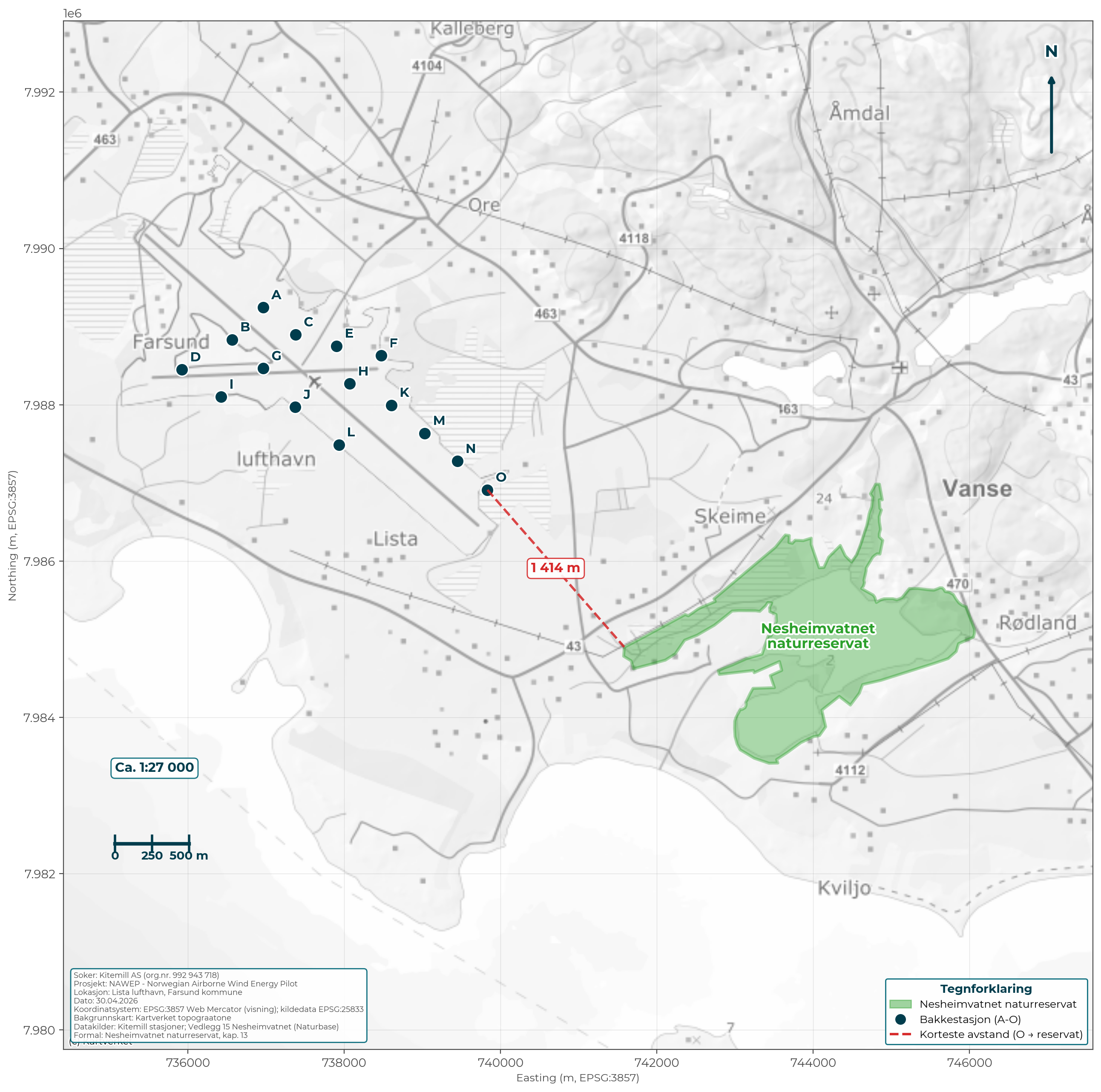 Figure 13.1: Overview map showing the planned station locations (A-O) in relation to Nesheimsvatnet nature reserve (green area). The nearest station (O) lies approx. 1.4 km from the reserve boundary.
Status of the protected area:
- Name: Nesheimsvatnet nature reserve
- Type of protection: Nature reserve
- Date of protection: Protected as part of the Lista wetland system
- Management authority: County Governor of Agder
Assessment:
- The plan area does not directly affect Nesheimsvatnet nature reserve
- The distance from the nearest station (O) to the reserve boundary is approx. 1.4 km
- AWE operation in the airspace above the airport will not directly affect wetland functions
- Birds migrating between Nesheimsvatnet and other wetlands (Slevdalsvannet, Lista wetland system) are monitored as part of the bird monitoring programme
Conclusion: The project does not affect the Nesheimsvatnet area directly. The distance from the nearest station to the reserve boundary is assessed as sufficient to avoid direct disturbance of wetland functions. Bird activity in the corridor between the wetlands is followed up through the monitoring programme.
14. CULTURAL HERITAGE AND CULTURAL ENVIRONMENT
14.1 WW2 cultural heritage
Lista Airport has extensive WW2 history:
| Cultural heritage |
Status |
Location |
| Runway and infrastructure from 1942 |
Protected |
Plan area |
| Hangar 45 (Festung Lista museum) |
Protected |
Plan area |
| Nordberg Fort |
Protected by the Directorate for Cultural Heritage |
> 3 km north |
| Marka battery |
Protected |
Plan area |
14.2 Automatically protected cultural heritage
Rock carving site at Penne:
- Approx. 3,000 years old (Bronze Age)
- 22 boats, two footprints, approx. 70 cup marks
- Location: North of the plan area, in West Lista cultural landscape
- Status: Automatically protected (older than 1537)
Hervoll Mill:
- Two old mill houses
- Location: East of Nordberg Fort
- Functions as a museum
14.3 Cultural landscape
West Lista selected cultural landscape:
- National status (KULA register)
- Stone walls and agricultural landscape
- Biodiversity and cultural heritage
- Norway's highest density of ancient monuments
Lista beaches landscape protection area (1987):
- 8,012.5 daa
- Distinctive natural and cultural landscape
- Geological, botanical and cultural-historical qualities
14.4 Festung Lista - historical context
Lista Airport was during WW2 part of "Festung Lista" - an extensive German military complex:
- Approx. 300 buildings erected by the occupying power
- Lundebanen (narrow-gauge railway to Lundevågen, opened 1943)
- Marka battery (field guns with 22 km range)
- Approx. 10,000 workers engaged in construction
Museums in the area:
- Festung Lista Hangar Museum (Hangar 45)
- Nordberg Fort (Directorate for Cultural Heritage protected, museum since 2009)
14.5 Assessment
The AWE plant:
- Does not directly affect ground-based cultural heritage
- No excavation or construction work near protected objects
- The ground stations are placed on existing asphalt surface
- Visual impact on the cultural landscape is assessed in section 10
- Operation in the airspace does not affect physical cultural heritage
15. PUBLIC HEALTH AND LIVING ENVIRONMENT
15.1 Nearest settlements
| Area |
Distance from nearest ground station |
Comment |
| Nordhassel (individual dwellings) |
approx. 770 m (from station N) |
South of runway |
| Råstad (individual dwellings) |
approx. 776 m (from station F) |
North/north-east of runway |
| Lista population centre |
approx. 1,400 m (from station D) |
West of runway |
| Borhaug population centre |
approx. 4,000 m (from station D) |
Further west |
15.2 Overall assessment
Based on:
- Noise (section 11): Within threshold values
- Visual impact (section 10): Moderate, reversible
- Shadow flicker (section 12): Negligible
- Outdoor recreation (section 13): Minimal impact
Overall assessment: Acceptable impact on public health and living environment.
15.3 Electronic communications (ekom)
An assessment of NAWEP's impact on electronic communications has been carried out in accordance with Nkom (Norwegian Communications Authority) and NVE's current guidelines for safeguarding electronic communications in wind power development (Nkom's revised guidelines effective from 1 October 2025).
15.3.1 Identified ekom actors and services in the area
The mapping of ekom infrastructure around Lista has been carried out through Nkom's web service Finnsenderen.no. The following categories have been identified as potentially relevant:
- Mobile network (4G/5G) from several operators
- Digital terrestrial network for TV (DVB-T2, operated by Norkring)
- Radio links from telecommunications companies
- Avinor – aviation communication, navigation and surveillance systems at Lista Airport
- The Norwegian Armed Forces' radar and communications systems (clarified through dialogue, cf. section 17.4)
During the consultation phase of the licensing process, Kitemill will make a formal enquiry to Norkring, the principal mobile network operators and Avinor in order to clarify any specific radio link routes and frequency allocations crossing the operating area, so that any substantiation of interference can be documented on a concrete basis.
15.3.2 Assessment of harmful interference from NAWEP
The risk of harmful interference to ekom networks from NAWEP is assessed as substantially lower than for conventional wind turbines for the following reasons:
- No rotating rotor blades providing Doppler interference to radar systems
- Lower reflective cross-section than conventional wind turbine blades (kite has less metal surface)
- Variable and less predictable position gives lower probability of persistent reflection zones
- Operating altitude 150-500 m is lower than typical radar shadow problem zones for transmission networks
Kitemill's command and control link (C2 link) operates in a licence-exempt SRD (Short Range Devices) sub-band under Nkom's general authorisations, harmonised with ETSI EN 300 220 and the European SRD allocation. The band is reserved for short-range telemetry and does not overlap with mobile networks, digital terrestrial broadcast (DVB-T2) or aviation VHF communications. Actual transmit power is substantially below the regulatory ceiling, and communication takes place only locally between kite and ground station. Operational airtime is within SRD framework limits; Kitemill verifies compliance through internal operational logs documented in the SQIS system.
15.3.3 Commitments and mitigation measures
Kitemill commits to:
- Contact relevant ekom actors as part of the consultation phase of the licensing process
- Implementation of any necessary mitigation measures in case of documented harmful interference, in accordance with Nkom's standard conditions
- Cooperate with ekom actors in substantiating interference and implementing mitigation measures as needed
It is proposed that the license decision include Nkom/NVE's standard conditions on mitigation measures in case of harmful interference.
15.4 Water and ground pollution
15.4.1 Emission sources
NAWEP has limited potential for water and ground pollution:
- Oil from Kitemill's internal transformers (3 x 450 kVA, oil-filled): Small volumes. The transformers are placed in upgraded substation 74013 with an oil collection system in accordance with standard grid industry practice.
- Generators: No fuel - clean electromechanical conversion from tether motion.
- Lubricant/hydraulics in winch: Small quantities, controlled service intervals.
- Batteries on kite (VTOL system): Lithium-ion. Risk of fire in the event of an unplanned landing - handled through procedures in the Operations Manual.
15.4.2 Risk assessment
The Lista area has adjacent wetland areas (Slevdalsvannet, Nesheimsvatnet - Ramsar). Risk assessment:
- Normal operation: No emissions expected
- Unforeseen incidents: Risk limited to local leakage from transformer construction or battery failure during an unplanned landing. Handled through emergency preparedness routines.
- Construction phase: Standard contractor practice for fuel and hydraulics handling in accordance with NS 8406.
15.4.3 Mitigation measures
- Oil collection system at substation 74013 (Glitre standard)
- Emergency preparedness plan for fire and emissions (OM rev. 4.0 chapter 7)
- Reporting of all deviations in accordance with QHSE system
- Routines for safe handling of batteries on kite
The consequence for water and ground is assessed as low, given normal operation and established emergency preparedness routines.
16. CO-USE AND COORDINATION
16.1 Current users of Farsund Airport
Lista/Farsund Airport is a multi-use arena. The following actors regularly use the airport area:
- Flying clubs (parking, maintenance, refuelling)
- Agriculture (sowing and harvesting of grass on and around the airport area)
- Kitemill AS (wind power production and R&D)
- Military drones, non-stationed air traffic, rescue services and events
16.2 Coordination principle
Established aviation, military activity and rescue services have priority over AWE operation. Kitemill's systems are designed for rapid landing, and operation is adapted to other activity.
16.3 Coordination measures
The following measures will be implemented in cooperation with Farsund Lufthavn AS:
- Time-slot-based planning: Operating periods are organised in blocks that can be reserved and cancelled with set deadlines, so that all parties have predictability.
- Dialogue and input meetings: Regular meetings with the airport's other users and the local community to adapt operating and operational pattern.
- Communication tools: Telephony and aviation radio are used for direct coordination, in line with established practice at airports.
16.4 Private airstrip
There is a private landing strip in the vicinity of station L. Kitemill is aware of this and will observe applicable rules for obstacle limitation surfaces and altitude restrictions also for this airstrip.
16.5 U-space airspace organisation
Kitemill plans to implement the European U-space regulatory framework (EU Regulation 2021/664) for the organisation of airspace activity at Farsund Airport. This entails the use of a USSP (U-space Service Provider), for example AirDodge, for coordination between AWE operation and other aviation activity. The experience from this implementation may form the basis for future airspace organisation at other AWE plants in Norway.
17. NATURAL HAZARDS AND SAFETY
17.1 Introduction
This chapter covers NVE's feedback point 3 (risk assessment) and point 4.9 (Norwegian Armed Forces), as well as points 4.3 and 4.8 (safety zones and marking). The content is structured as follows:
- 17.2 Safety and risk management (SORA regime)
- 17.3 Experience and systematic learning
- 17.4 The Norwegian Armed Forces and coordination in the airspace
- 17.5 CAA-N's assessment
- 17.6 Ice throw
- 17.7 Flood and landslide hazard
17.2 Safety and risk management (SORA regime)
17.2.1 Regulatory framework and pathway
NAWEP's air operations are regulated by EU Regulation 2019/947, implemented in Norway through regulation 2024-11-01-2777 (BSL A 7-2 on unmanned aviation, Norwegian regulation on unmanned aviation, implementing EU 2019/947), and are conducted in accordance with the SORA methodology (Specific Operations Risk Assessment). Kitemill has established a documented regulatory pathway through the gradual extension of operating permits for the KM1 system:
| Milestone |
Date |
Reference |
Type of operation |
SAIL level |
| First VLOS operating permit KM1 |
12.01.2023 |
22/02391-20 / NOR.OA.000141 |
VLOS, Day only |
SAIL II |
| Updated VLOS operating permit KM1 |
20.01.2025 |
22/02391-46 |
VLOS |
SAIL II |
| BVLOS operating permit KM1 |
16.10.2025 (valid until 16.10.2027) |
22/02391-68 / NOR-OAT-000294/000 |
BVLOS |
SAIL II |
| VLOS Training UAVs |
18.12.2025 |
22/02391-77 |
VLOS |
SAIL II |
The BVLOS approval from October 2025 is the most relevant for the NAWEP project and demonstrates that Kitemill's operating pattern is approved for continuous operation without pilot line-of-sight, and that CAA-N has accepted SAIL II risk level (Sparsely populated, ARC-a operationally / ARC-c adjacent, M1 and ERP medium) and operations at Lista Airport (the D257 area, upper limit 4,000 ft AMSL = 1,220 m).
17.2.2 Containment for NAWEP
NAWEP's containment (SORA Basic, cf. point 4.13 of the BVLOS authorisation) is established through four layers, documented in Kitemill's Operations Manual QP-OPS-001 (the BVLOS authorisation NOR-OAT-000294/000 of 16.10.2025 refers to rev. 3.0; the current version is rev. 4.0, CAA-approved January 2026):
1. Tether tethering and operating volume
The tether system physically restricts the kite's movement to a hemisphere around the ground station. The ground impact zone in case of total failure is inherently limited to approx. a 1:1 ratio between operating altitude and horizontal distance. The operating volume consists of a flight volume (in which the kite is to operate) and a contingency volume (the volume reserved for recovery upon control deviation).
2. Ground risk classification
In accordance with Kitemill's BVLOS operating permit (NOR-OAT-000294/000, 16.10.2025), the operational area is classified as Controlled ground area and sparsely populated areas (combination), and the adjacent area as sparsely populated. The kite operates primarily within Lista Airport's secured industrial area, but the operating volume may also extend beyond the airport fence in accordance with the operating permit. The ground risk buffer - the area in which the kite could potentially fall - lies within a sparsely populated agricultural and forest area without residential buildings, confirmed through population data (cf. fig. 4.9 and 4.10 in section 4.9).
3. Air risk buffer - EN D257
Kitemill has established danger area EN D257 as an airspace barrier. The area is announced through NOTAM at least one week before operations. It defines separation from other civil aviation and has an upper limit of 4,000 ft AMSL (1,220 m). The vertical extent of the danger area to 1,220 m constitutes a regulatory reserve against other aviation; the maximum operating altitude for each kite unit is 500 m above ground (cf. section 4.6), and the operational volume therefore uses only a smaller part of the reserved airspace.
4. Contingency procedures and automatic flight termination
OM rev. 4.0 chapter 5.2 specifies dedicated contingency procedures for each identified failure mode. NAWEP is a BVLOS operation, and the following applies:
- Automatic flight termination with return-to-home function is activated. The function is triggered either manually upon loss of control, or automatically if the kite leaves the contingency volume.
The return-to-home function was extended and demonstrated in February 2026. The function fulfils the regulatory flight termination requirement by bringing the kite back to the ground station within the operating volume, and at the same time provides operational value through intact landing of the aircraft.
Together, these four layers constitute NAWEP's containment architecture and satisfy the SORA Basic containment requirements. Enhanced containment may be considered in future updates of the SORA documentation based on actual operational data, together with CAA-N.
17.2.3 NAWEP as further development (KM2)
The NAWEP project builds on the KM2 system, a further development of KM1. KM2 differs from KM1 in the following respects:
- Rated capacity 100 kW (vs 30 kW for KM1)
- Larger wing and tether
- Permanent installation (ground stations mounted, not mobile test set-up)
- Simultaneous operation of 15 systems
NAWEP therefore requires an updated SORA and a new operating permit from CAA-N for the KM2 operation. The SORA update is prepared and submitted to CAA-N ahead of phase 2 of project execution, in parallel with financing and engineering, so that the updated operating permit is in place before installation of the KM2 systems begins. The transition from SORA V2.0 to SORA V2.5 (JARUS 2024, implemented 2026) will be part of this process.
Kitemill's track record of three completed operating permits over 3 years (VLOS, BVLOS, Training UAVs), together with active dialogue with CAA-N, makes it likely that a corresponding approval will be obtained for the KM2 operation before commissioning of phase 1 (planned 2027).
17.2.4 Fact box: SORA 2.5 and NAWEP/KM2
FACT BOX: SORA 2.5 and NAWEP/KM2
What is SORA 2.5?
SORA is the methodology the EU uses to approve operations with unmanned aircraft in the specific category. Version 2.5 was published by JARUS in November 2024 and gradually replaces version 2.0 through 2026.
Most important changes from SORA 2.0 to 2.5:
| Area |
SORA 2.0 |
SORA 2.5 |
| Intrinsic GRC table |
10 scenarios |
New iGRC table with explicit numerical population density intervals |
| Containment |
Basic / Enhanced qualitative |
Basic / Enhanced with detailed technical and assurance requirements |
| Anchored UAS |
General provisions |
Specifically addressed with its own pathway |
| OSO structure |
24 OSOs |
Restructured into clearer groups |
KM2/NAWEP adaptation: Compensated through tether tethering (inherent ground risk buffer limitation 1:1), operational restrictions and well-established procedural structure. Kitemill has active dialogue with CAA-N's section for unmanned aviation (contact: August Holte, flight operations inspector).
17.2.5 Safety around ground stations
The current wording on "safety zones around ground stations" is corrected here. Safety around the ground stations is ensured through operational regime, not through geometric circles:
- Physical security: The ground stations are installed within Lista Airport's secured industrial area with access control
- Working area: Approx. 25 m² gravel pad around each ground station for inspection and maintenance
- Operational routine: Maintenance only takes place during operational shutdown. No access for non-operational personnel during flight
- Monitoring: Continuous remote monitoring from control room
17.2.6 Margin to densely populated area
The population map (fig. 4.9) shows that the nearest "populated"-classified area (Borhaug) lies approx. 5 km from the plan area. Vanse and Farsund lie 6-7 km east. These distances are substantially greater than the relevant Ground Risk Buffer.
17.3 Experience and systematic learning from the development period
17.3.1 Principle for Kitemill's safety culture
Kitemill has, since 2008, worked according to the principle that every incident shall provide a basis for concrete improvement. This is operationalised through:
- Safety, Quality and Improvement System (SQIS)
- Reporting to CAA-N via NF-2007 form in accordance with EU 376/2014
- Systematic updating of the Operations Manual (now rev. 4.0)
- Periodic audits and dialogue with CAA-N - identified deviations are systematically resolved and closed
17.3.2 Earlier incidents and follow-up
During the development period 2015-2026, Kitemill has had a small number of unplanned landings of test aircraft at the Lista test plant. All incidents have occurred within classified and controlled ground area, and none have resulted in personal injury or damage to third-party infrastructure.
Each incident has been analysed for root cause and has provided the basis for concrete technical, operational and organisational measures. A full incident log and risk assessment is documented in Appendix 08 - Risk assessment NAWEP.
17.3.3 Learning translated into measures
| Incident category (learning from) |
Specific measure introduced |
| Loss of control upon transition automatic↔manual mode |
Redundant control system. Explicit confirmation upon critical mode changes. Revised pilot procedure in OM. |
| Loss of control with radio equipment |
Revised failsafe requirements for transmission equipment. Automatic safe state in the event of radio loss. |
| Energy shortage during prolonged flight |
Redundant battery and charge monitoring. Operational operating time restrictions. Automatic return-to-base on low reserve. |
| Uncontrolled fly-away (soft kite system) |
Tether load monitoring with deviation detection. Automatic activation of contingency procedures upon deviation from the contingency volume. |
| Unstable flight in marginal wind |
Low-wind algorithm and turbulence prediction developed in 2026. |
| Operational consolidation during BVLOS scale-up |
Extended pilot training for BVLOS. Control room monitoring. Revised Standard Operating Procedures. CAA dialogue resulted in BVLOS operating permit (NOR-OAT-000294/000, 16.10.2025). |
| Classification and handling of ground area |
Pre-flight checklist for ground area. Permanent danger area EN D257 established. Observer role for endurance operations over controlled ground area. |
| Documentation and reporting routines |
Operations Manual updated to rev. 4.0 (CAA-approved). Systematic QHSE reporting. |
| Pilot ergonomics and fatigue |
Operating time restrictions per pilot. Rotation between control room pilot and field team. IMSAFE assessment at each shift. |
17.3.4 Maturation over time
- Extended CAA approvals: VLOS (2023) → updated VLOS (2025) → BVLOS SAIL II (2025) → planned KM2 approval (2027-28)
- Operations Manual: rev. 1.1 (2023) → rev. 4.0 (2026), CAA-approved
- Incident rate per flight hour has been reduced over time (documented in QHSE KPI reporting to the Board)
- Share of autonomous flying continually higher - reduces operational burden
- Flight termination function: originally pilot-initiated tether release and manual landing (VLOS), extended in 2026 to automatic return-to-home (BVLOS)
17.3.5 NAWEP: from development to permanent operation
The transition from development phase to NAWEP's commercial operation further strengthens the safety regime:
- Permanent installation within Lista Airport's secured industrial area with access control
- Automatic flight termination with return-to-home for BVLOS - technology developed as part of the KM1 maturation
- Established and approved OM structure carried over to KM2
- Continuous professional monitoring and reporting to CAA-N and NVE
17.3.6 Risk register NAWEP
Pursuant to NVE's feedback (18 March 2026, point 3), an explicit risk register has been prepared for both unintentional and intentional incidents. The table below is a summary from Appendix 08 (Risk assessment NAWEP, prepared by CTO Marius Dyrset). Probability and consequence classes follow the DSB risk matrix (Low / Medium / High). The risk class is the resultant of P x C, where P = probability and C = consequence.
| # |
Incident |
P |
C |
Risk class |
Mitigation measures |
| 1 |
Unplanned landing of kite (loss of control or battery loss) |
Low |
Low |
Low |
Containment architecture (cf. section 17.2.5); automatic flight termination with return-to-home; geo-fence 400 m; fire preparedness in case of battery damage (cf. section 15.4); observer on duty during operation |
| 2 |
Tether failure (line break) |
Very low |
Medium |
Low |
Certified HMPE tether with 4x safety factor; daily pre-flight inspection; continuous load monitoring; automatic safe state in case of abnormal load history |
| 3 |
Tether crossing (between KM2 systems or between kite and other aircraft) |
Low |
High |
Medium |
Geo-fence at 400 m sphere isolates each station; separation distance 800-1,000 m between stations; BVLOS procedures for simultaneous operation; danger area EN D257 separates NAWEP airspace from other civil aviation; ongoing coordination with the Norwegian Armed Forces (cf. section 17.4) |
| 4 |
Power outage (at ground station or from distribution grid) |
Medium |
Low |
Low |
UPS battery backup on control system; automatic safe state on power loss; pre-planned landing within 5 minutes on reserve battery; redundant communication (Direct + network C2 link, cf. BVLOS authorisation point 4.7) |
| 5 |
Fire (in ground station, kite, battery or transformer) |
Low |
Medium |
Low |
Fire/smoke detectors in ground station; oil collection trays beneath transformers; battery management system with thermal runaway detection; fire preparedness plan in OM rev. 4.0 chapter 7; extinguishers on site; alarm to the 110 emergency centre |
| 6 |
Extreme weather (storm, lightning, icing, freezing rain) |
Medium (seasonal) |
Medium |
Medium |
Real-time weather monitoring with automatic departure at cut-out (24 m/s); thunder/lightning detection with automatic retrieval and landing; ice-warning mode with early return on frost forecasts; extreme weather procedures in OM |
| 7 |
Technical failure (sensor, actuator, communication, generator) |
Medium per component |
Low |
Low |
Redundant sensor/actuator architecture (2-out-of-3 voting where relevant); automatic degraded mode on single failure; real-time health monitoring with automatic landing on critical failure; planned maintenance pursuant to NS 8407 |
| 8 |
Total loss of kite with descent into controlled ground area |
Very low |
Medium (local damage to airport infrastructure) |
Low |
Four-layer containment architecture (cf. section 17.2.5); automatic flight termination system; geo-fence ensures fall within classified ground area; no third-party infrastructure in the contingency volume; pre-flight inspection of the ground area |
| 9 |
Intentional incidents (sabotage, cyber attack, physical intrusion, hostile drone) |
Low |
High |
Medium |
Access control to Lista Airport's secured industrial area with perimeter fence and CCTV; encrypted C2 link with authentication and integrity check; redundant command/control channel; continuous security monitoring; cooperation with NSM and the Norwegian Armed Forces on airspace surveillance (cf. section 17.4); security protocol in OM rev. 4.0 |
The risk matrix is aligned with Kitemill's CAA-N approved SORA V2.0 assessment (BVLOS operating permit NOR-OAT-000294/000, SAIL II), which identifies ARC-a as the residual airspace risk in the operational volume and ARC-c in the adjacent volume, with M1 and ERP at medium level (cf. authorisation points 3.8 and 3.10).
Conclusion: After mitigation measures, all identified incidents lie at risk class Low or Medium. No risk is classified as High. Incidents in the Medium class (tether crossing, extreme weather, intentional incidents) have dedicated procedures in Operations Manual rev. 4.0 and are subject to continuous follow-up in Kitemill's QHSE system.
17.4 The Norwegian Armed Forces and coordination in the airspace
17.4.1 Existing dialogue and coordination
Through 2025-2026, Kitemill has established an active and constructive dialogue with the Norwegian Armed Forces' Drone Services, which also has an operational presence at Lista. The dialogue covers coordination of simultaneous use of the airspace, exchange of information about operational time windows, and assessment of possible technical and operational integration points.
The Norwegian Armed Forces have applied for a restricted area which in practice gives the Armed Forces priority access to the air volume. Neither Kitemill nor the Armed Forces consider this problematic, as use can be coordinated, and large parts of operations can be conducted simultaneously within dedicated time windows or through dynamic coordination.
Status of formal coordination: The dialogue is, as of April 2026, in an operational phase. Formal written statements from the Norwegian Armed Forces / Norwegian Defence Estates Agency will be obtained and documented as part of NVE's consultation process, so that the consultation responses are available at the same time as NVE processes the application. Correspondence from the Norwegian Armed Forces' Drone Services with relevance to co-use coordination will be forwarded as a consultation input when available.
17.4.2 U-space as a future coordination mechanism
Kitemill and the Norwegian Armed Forces have expressed a common interest in considering U-space as a relevant coordination platform for unmanned aviation in the area. U-space is the EU's regulatory framework for safe and efficient operation of a larger number of unmanned aircraft in defined airspace, and may provide real-time coordination between civil and military operations in a robust manner.
17.4.3 The Armed Forces' overarching prerogatives
The NAWEP project will respect that the Armed Forces in all cases safeguard their obligations relating to emergency preparedness and protection of critical societal functions. This includes the Armed Forces' need for Control and Reporting (K&V) in the airspace, the Armed Forces' ability to assert national sovereignty, as well as emergency preparedness considerations and national security.
Kitemill expects that the Armed Forces, as in earlier consultation processes, will focus on ensuring that new plants in the airspace do not reduce the Armed Forces' capacities in control, reporting and communications. NAWEP's technical and operational solutions have been developed with this consideration in mind.
17.4.4 Societal benefit through cooperation
Through 2025-2026, Kitemill has been in dialogue with various branches of the Armed Forces about potential cooperation where Kitemill's airborne wind technology can support the Armed Forces' needs. The cooperation has two main dimensions:
A) Capabilities from continuous airspace presence (ISR and communications):
- Control and reporting through continuous airspace presence
- Communications support
- Surveillance of coastlines, borders and critical infrastructure
- Real-time ISR services (Intelligence, Surveillance, Reconnaissance)
B) Portable renewable energy production:
AWE represents, for the first time, a renewable technology that can be moved. A KM2 plant, of which NAWEP will test multiple instances, alone produces energy equivalent to 12-15 truckloads of diesel annually. This provides unique operational applications for the Armed Forces:
- Energy supply to command posts in areas without established infrastructure
- Emergency power for vessels or forward operating bases
- Strategic reduction of logistics vulnerability - fossil supply chains have historically been a priority target in combat and conflict. Portable on-site energy production substantially reduces this dependence
- Supply for forward operations where ground-based energy infrastructure is not practicable
- Energy security in the event of natural disasters, cyber incidents or other situations where normal infrastructure is compromised
17.4.5 Expected assessment
Kitemill assumes that the Armed Forces, when assessing NAWEP, will take necessary reservations regarding long-term emergency preparedness considerations, will use the knowledge built up in NAWEP as a basis for future operational decisions, and will initially assess that the advantages of the project are greater than the disadvantages, based on already established dialogue and the documented coordination basis.
17.5 CAA-N's assessment
CAA-N has, in a consultation statement to Farsund municipality (May 2025), stated:
"CAA-N is generally positive towards technological development in the drone industry, and has no objections to using Lista Airport for testing purposes as long as air and ground risk are addressed through existing and any new approvals."
CAA-N has further recommended that Kitemill apply for new airspace restrictions around the operating area to safeguard the safety of other air traffic at full-scale demonstration plant. Kitemill will follow this recommendation through the SORA update for KM2 and dialogue with CAA-N.
17.6 Ice throw
Note: For conventional wind power, ice throw from rotor blades constitutes a documented risk. For AWE systems, this issue is substantially different.
In icing conditions, the AWE system will:
- Automatically land (cannot fly with ice on the wing)
- Not operate under icing conditions
- Risk of ice throw is assessed as negligible
17.7 Flood and landslide hazard
The plan area lies on flat ground at Lista Airport. The area has varied surface - asphalt runway, taxiways and ring roads with concrete surface, as well as cultivated land where the ground stations are placed. The risk of landslides is assessed as negligible due to the flat topography.
For flood risk, station locations will be assessed against the 20-year flood. Where local ground conditions so indicate, the terrain will be raised with fill or drainage will be improved to secure the ground stations. The temporary nature of the project and container-based ground stations mean that the plants can be moved as needed.
18. CUMULATIVE IMPACT
18.1 Existing burden in the area
The Lista area already has:
- Airport with air traffic
- Agricultural activity
- Tourism and outdoor recreation
- Existing infrastructure
18.2 Cumulative effects
| Factor |
Existing |
AWE contribution |
Combined |
| Noise |
Air traffic |
Low addition |
Acceptable |
| Visual |
Hangars, buildings |
Moderate |
Acceptable |
| Birds |
Air traffic, agriculture |
Monitored |
Addressed through monitoring programme |
18.3 Other plans in the area
It is not known that there are other planned energy projects or larger development projects in the immediate vicinity of the plan area that would entail further cumulative burden. Solkraft Lista AS has plans for a solar cell installation at the airport area, and this project is coordinated with NAWEP through joint grid connection.
19. ZERO ALTERNATIVE
19.1 Definition
The zero alternative is the situation if the NAWEP project is not implemented.
19.2 Consequences of the zero alternative
Energy production and climate targets
If the project is not implemented, no renewable energy will be produced from AWE technology in Norway. At mature operation, the project may deliver up to 4.2 GWh annually to the regional grid (price area NO2), which in recent years has had higher power prices than other price areas in Norway (cf. section 2.4.1). Based on the EU Innovation Fund's calculation methodology (emission factor 0.15 tonnes CO2e/MWh), this corresponds to an annual greenhouse gas saving of about 630 tonnes CO2 equivalents at mature operation.
Norway has committed to a 55% emission reduction by 2030 and 70-75% by 2035. The Norwegian Energy Commission has identified a need for at least 40 TWh of new power production. Although NAWEP in isolation represents a limited volume, the project's primary climate contribution is to develop and document a technology which, with commercial scaling, can give a substantially larger contribution with lower resource use than conventional alternatives.
Knowledge building and biodiversity
Without NAWEP, no systematic knowledge will be built up regarding the interaction between AWE technology and Norwegian nature. The project is designed to generate data on bird activity, visual impact, noise and operational adaptations that will form the basis for knowledge-based management in any future roll-out of AWE in Norway. This knowledge cannot be replaced by experience from other countries, as local natural conditions and migratory routes are site-specific.
The existing burden on the plan area from air traffic and agriculture will continue unchanged regardless of the zero alternative.
Technology development and Norwegian industrial position
Through Kitemill, Norway has a significant position in the AWE sector internationally. The company is among the most established and active developers of airborne wind energy globally. If NAWEP is not implemented, this position may be weakened. Technology development will continue in other countries - Germany has already introduced a feed-in tariff for AWE, and several European actors are preparing demonstration plants. The EU has invested EUR 3.35 million in NAWEP through the Innovation Fund, and a failure to implement will reduce Norwegian influence on the technology's further development and future regulation.
Local value creation
The zero alternative entails that no jobs or R&D activity related to AWE are created at Lista. The airport's suitability as a location for renewable energy production and technology development will not be tested, and the region will miss out on associated business development and competence-based jobs.
19.3 Assessment
The zero alternative entails that the opportunities for climate transition, knowledge building, local value creation and Norwegian industrial position within an emerging technology will not be realised. The project's mitigation measures are designed to limit impact on biodiversity to a minimum, and the limited reduction in burden that the zero alternative entails must be weighed against the opportunities the project represents.
19.4 Quantitative balance: benefits and drawbacks against the zero alternative
In line with NVE's feedback (18.03.2026, point 2), this section presents a quantitative comparison of the project's benefits and drawbacks against the zero alternative (no development). The figures represent the expected operating point after commissioning (mature operation from 2029) and are based on Kitemill's own calculations, external tenders, EU Innovation Fund reporting and publicly available references.
19.4.1 Direct quantitative benefits
| Topic |
Zero alternative |
NAWEP implemented |
Net benefit |
| Renewable energy production |
0 GWh/year |
4.2 GWh/year (1.2 MW × 3,500 full-load hours) |
+4.2 GWh/year — power equivalent to approx. 270 Norwegian households (15,500 kWh/year) |
| Greenhouse gas reduction (EU IF methodology) |
0 tonnes CO2e/year |
630 tonnes CO2e/year (0.15 t/MWh × 4.2 GWh) |
+630 t CO2e/year — equivalent to approx. 274 Norwegian passenger cars' annual emissions (2.3 t/car) |
| Permanent land use per MWh produced |
n/a |
520 m² / 4,200 MWh/year = 0.12 m²/MWh |
Approx. 1/30 of conventional onshore wind power (typically 3-4 m²/MWh including roads and foundations) |
| Material consumption per MW installed |
n/a |
~50 tonnes (kite + ground station + tether per 100 kW × 15) |
Substantially lower than conventional 1.2 MW HAWT (typically 200-400 tonnes including foundation). Kitemill estimate, to be verified through NAWEP |
| Reversibility at project end |
n/a |
100 % reversible — no permanent concrete foundations or access roads |
Complete area restoration possible (cf. section 20.2.5) |
19.4.2 Indirect quantitative benefits
| Topic |
Zero alternative |
NAWEP implemented |
Net benefit |
| Secured EU/international funding |
0 EUR |
EUR 3.35 million (EU Innovation Fund, NAWEP programme) + AWE-KM2 (Horizon Europe Grant 101189207) + AWETRAIN doctoral training network (MSCA Grant 101168734) + 3D-Circular (HaDEA Grant 101226256) |
EUR 3.35M+ directly to NAWEP, total EU funding for Kitemill approx. EUR 9-10M for Lista-related R&D |
| Local investments (CAPEX) |
0 NOK |
76-85 MNOK over the installation phase, of which approx. 3.4 MNOK directly to a local contractor (Grunnlink, Lista) for civil works |
76-85 MNOK invested in the region 2026-2028, with a substantial share to local suppliers |
| Operating phase OPEX (annual) |
0 NOK |
3.5-5.0 MNOK/year (operations, R&D, bird monitoring, insurance, ground rent) |
3.5-5 MNOK/year continuous regional activity over the 3+ year operating phase |
| Direct employment in operations |
0 FTE |
5-8 FTE at Kitemill (Lista + HQ Vågsbygd) |
Permanent R&D activity in the Lister region + indirect employment at Glitre Nett, Grunnlink and local service providers |
| Academic and industrial competence |
n/a |
Doctoral positions via the AWETRAIN network (NTNU/TU Delft); master's and bachelor's supervisors; technical field data to IEA Wind Task 48 |
Norway retains a competence base in an emerging sector; export volume for knowledge and IP |
| Data points for knowledge-based regulation |
0 |
3+ years of continuous data on noise, bird behaviour, AWE performance under Norwegian conditions; public publication of key results |
Dataset available to NVE, the County Governor, municipalities and academia for future AWE applications |
19.4.3 Strategic benefits (qualitative, but measurable through positioning)
- Norwegian industrial position in AWE: Kitemill is among the world's 5 most established AWE actors (as of 2026, per IEA Wind Task 48 and the European AWE Conference). Germany introduced a feed-in tariff for AWE in 2024 (EEG); several European countries are planning demonstration plants. NAWEP secures Norwegian leadership; the zero alternative weakens this position.
- Patent and IP portfolio: Kitemill's patents cover core elements of the KM system (VTOL launch, power generation, geofence control). NAWEP data strengthens the patents' practical validation and Kitemill's negotiating position vis-à-vis international partners/licensees.
- EU regulatory influence: As an active participant in EU IF, Horizon Europe and MSCA, NAWEP gives Norway influence on the framework for AWE — important for future export opportunities.
- Complementary to other renewable sources: AWE has a complementary correlation with hydropower and solar power (stronger wind at altitude during certain weather systems). To be verified through NAWEP.
- Demonstration value for industry and authority decisions: Actual operating data from Norwegian conditions provides an empirical basis for future AWE licensing in Norway — infrastructure that would otherwise have to be established later with greater uncertainty.
19.4.4 Quantified drawbacks / costs (cf. chapters 8-17)
| Topic |
Quantified impact |
Mitigation measures (cf. chapter 20) |
| Permanent land use |
approx. 520 m² (0.05 ha) within the airport's existing industrial area |
100 % reversible; no new roads; no protected areas affected |
| Temporary land disturbance during construction |
approx. 7,700 m² (cable trenches, lay-down area, drilling pits) |
Restoration after construction; no permanent terrain interventions |
| Noise (Lden) at nearest dwelling |
< 45 dB(A) (below T-1442/2021 limit value) — Nordhassel approx. 770 m, Råstad approx. 776 m |
Bouman measures (-10 dB Lw_kite), night shutdown M/N/O 23-07, geofence 400 m, measurement programme 1 week/quarter year 1 (cf. section 11.7) |
| Visual impact |
Kites visible from approx. 3-5 km on a clear day; ground stations approx. 3 m high |
Reversible; only visible during operation; low visual signature compared to conventional towers (80-150 m) |
| Birds |
Potentially sensitive impact; expert assessment for 15 systems by Arnold Håland/NNI (cf. chapter 9) |
Phased ramp-up (1-3-15 systems over 3 years), shutdown during migration periods, continuous AI camera + manual monitoring, adaptation commitment upon notified incidents |
| Risk (undesired incidents) |
After mitigation: all 9 NVE-specified incidents classified Low or Medium; none High (cf. section 17.3.6 risk register) |
Four-layer containment architecture, automatic return-to-home, certified SAIL II BVLOS approval valid until 16.10.2027 |
| Biodiversity (Slevdalsvannet, Nesheimsvatnet) |
Direct contact: 0. Indirect impact assessed as limited (distance 330 m and 1,400 m respectively from the nearest station) |
Monitoring programme documents actual indirect impact; adaptations committed upon any findings |
19.4.5 Industrial scaling potential — from NAWEP pilot to European production
NAWEP is deliberately designed as a direct precursor to Kitemill's industrial scale-up. The company submitted on 23.04.2026 an application to the EU Innovation Fund 2025 (Clean Tech Manufacturing) for FJORD — the first vertically integrated AWE factory in Europe, with Lista as a candidate location (Letter of Intent from Venturos AS for industrial-zoned land at Lista, signed 21.04.2026).
| Parameter (FJORD at mature operation, 2035) |
Value |
| Direct factory employment |
1,330 FTE |
| Annual production |
2,800 systems/year (KM1 ISR + KM2 commercial in parallel) |
| Annual production capacity |
176 MW/year |
| Cumulative installed capacity 2027-2038 |
~1,136 MW |
| Cumulative greenhouse gas avoidance 2027-2038 |
~3.5 Mt CO2e |
| Cost efficiency (CAPEX-based) |
~EUR 10/tCO2 |
| Total factory CAPEX |
EUR 35 M (60 % EU IF, 40 % equity + partners) |
| Factory opening |
Q3 2029 |
Employment beyond a single factory: 1,330 FTE covers only one KM1+KM2 factory. The ISR market alone requires more production lines than a single factory can deliver against known demand; equivalently, additional factories or expansions are anticipated for commercial KM2 volume as the market matures. Employment in the supplier chain comes in addition.
Norwegian supplier position — critical components:
The FJORD factory sources from a European supplier network where Norway has historical and ongoing leadership in several categories:
| Component |
Volume 2035 |
Norwegian supplier position |
| Winch (20-100 kW) |
2,800 units/year |
The Norwegian marine winch industry has a historical leadership position in offshore, fisheries and aquaculture, and is a priority supplier base for the FJORD factory |
| Composite structures (airframe) |
~35 t prepreg/year |
Eker Group (composite MoU under preparation), High Performance Composite AS (current Norwegian supplier) |
| Tether (UHMWPE rope) |
tens of km/year of aerospace grade |
The Norwegian fibre-rope industry has a strong position in offshore and marine applications |
| Wire harness, battery, sensors |
2,800 sets/year |
Norwegian/European suppliers preferred; standardised industrial electronics |
| Power electronics and frequency converters |
2,800 sets/year |
Norwegian industry has a strong position (the ABB heritage, suppliers in the electrical-engineering ecosystem) |
Connection NAWEP - FJORD: NAWEP delivers the technical and regulatory maturation that is a precondition for the FJORD investment. Industrial and institutional partners will not commit to a EUR 35M factory without having seen the technology operate under a Norwegian licensing regime. Refusal or delay of NAWEP therefore weakens not only the local project, but also the basis for FJORD being built in Norway rather than in another European country.
19.4.6 AWE as disruptive technology in the global energy market
The physical properties of AWE technology open for substantial expansion of globally available renewable resource:
Wind resource at 200-400 m operating altitude:
- Wind speeds are typically 2-3 times higher than at conventional hub height (80-150 m)
- Power potential grows cubically with wind speed — operating altitude provides substantially higher energy density and a more consistent capacity factor
- Less variability than at ground level gives better grid interaction and reduced need for balancing reserves
Geographical reach:
- Conventional wind power is economically viable in limited parts of the global land area (mainly coastal or high-mountain belts with sufficient wind speed at hub height)
- AWE systems at 300-400 m can exploit wind resource in a substantially larger share of the global area — including low-wind regions at the surface, islands with weak grids, topographically difficult areas and areas with land-use conflicts against tall towers
- This expands the addressable market segment significantly compared with conventional wind power
Consequence for the energy transition:
- AWE enables local power production in areas where conventional wind power is not considered relevant, without conflicts associated with tall permanent towers, access roads or concrete foundations
- Global applications: replace fossil baseload sources in regions with weak grids (developing markets), island states, Arctic operations, forward military bases, industrial off-grid activity
- Complementarity with hydropower and solar (cf. fig. 2.4.1) strengthens supply security in Southern Norway in particular
NAWEP's role in the global context: As the first licensed AWE plant in Norway under the revised BSL A 7-2 regime (2024), NAWEP is the demonstration that opens the Norwegian and European market for a technology with disruptive potential in the global energy market. Refusal weakens Norwegian industrial position in an emerging sector where technological, regulatory and market leadership are being shaped now.
19.4.7 Net assessment
Quantified against the zero alternative, NAWEP delivers +4.2 GWh/year of renewable energy, +630 t CO2e/year of climate savings, and 76-85 MNOK in direct regional investment against a permanent land use of 0.05 hectares and impacts which, after mitigation measures, lie below the T-1442/2021 limit value for noise and without documented unacceptable consequences for birds or biodiversity. In addition, EUR 3.35M+ in EU funding is secured for NAWEP itself, and the project lays the foundation for the EUR 35M FJORD factory investment (1,330 FTE at mature operation) which, with national location, will build a Norwegian supplier and competence ecosystem in a sector with disruptive global potential.
The relationship between quantified benefits and drawbacks, combined with 100 % reversibility at project end and a phased approach that allows iterative assessment, indicates that NAWEP overall provides a substantial net positive societal and environmental benefit compared with the zero alternative — both directly in the pilot phase and indirectly through industrial and technological scale-up.
20. MITIGATION MEASURES AND COMMITMENTS
This chapter brings together all mitigation measures and commitments across the topical chapters. For fuller descriptions, reference is made to the respective chapters.
20.1 Measures matrix per topic
20.1.1 Noise (cf. section 11.7)
| Measure |
Description |
Period |
Effect |
| KM2 design optimisation |
TE design, BL tripping, helical strake, tether design, wing profile |
2026 (design) → operation |
-10 to -15 dB Lw_kite |
| Per-kite buffer 430 m |
Geo-fence around the nearest dwelling |
Operation |
Ensures Lp_single ≤ 45 dB |
| Night shutdown M, N, O |
Stations M, N and O are not operated 23:00-07:00 |
Continuous operation |
-3 to -5 dB during night period |
| Selective shutdown of nearest station |
At critical wind direction towards dwelling |
Dynamic operation |
-1 to -3 dB at specific hours |
| Operational optimisation |
Speed, altitude, AoA, direction, line length |
Continuous |
-2 to -10 dB |
| Neighbour forum with Nordhassel/Råstad |
Direct dialogue in case of perceived burden |
Continuous (≥ annual meeting) |
Adjustment as needed |
| Acoustic measurement programme |
Source noise + immission at settlements |
Within 6/12 months of commissioning |
Verification Lden ≤ 45 dB |
20.1.2 Biodiversity and birds (cf. chapters 8 and 9)
| Measure |
Description |
Period |
Effect |
| Phased ramp-up |
From 1 to 15 systems over 3 years |
2026-2028 |
Gradual knowledge building |
| Daytime flying only in start-up phase |
Avoids night-time migration activity |
2026 |
Reduces nocturnal collision risk |
| Limited night flying under observation |
Only when detection equipment is operational |
2027 |
Verified night operation |
| Operational shutdown in busiest migration period |
Spring and autumn migration |
2028+ |
Eliminates collision risk in high-risk periods |
| Bird monitoring (field campaigns) |
Seasonal campaigns spring, summer, autumn |
2026-2031 |
Factual basis for evaluation |
| Selective operational shutdown M, N, O |
Stations closest to Slevdalsvannet at sensitive wind direction |
Operation |
Reduces impact on water birds |
| Continuous collision monitoring |
AI-based cameras + manual search |
Continuous operation |
Documentation of actual impact |
| Annual evaluations |
Acceptable impact must be documented before continued operation |
2029-2031 |
Adaptive management |
20.1.3 Landscape and visual impacts (cf. chapter 10)
| Measure |
Description |
Period |
Effect |
| Low ground stations (~3 m height) |
Little visible from ground level |
Operation |
Limited visual impact |
| Reversibility |
Steel frames, no concrete foundation |
Decommissioning |
Full restoration possible |
| Operation only at production wind |
Kites not visible without wind |
Operation |
Less exposure than conventional wind power |
| No light marking beyond BSL E 2-1 minimum |
Reduces light pollution at night |
Operation |
Protects dark sky |
20.1.4 Outdoor recreation and outfield use (cf. chapter 13)
| Measure |
Description |
Period |
Effect |
| Operation within the airport's fence |
No new land interventions in outfield |
Operation |
No new barriers for outdoor recreation |
| Information boards |
At hiking routes with view of the plant |
Start-up |
Information for hikers |
| No impact on Lista beaches |
Operation entirely within airport |
Operation |
Protects central recreation area |
20.1.5 Public health and living environment (cf. chapter 15)
| Measure |
Description |
Period |
Effect |
| Noise measures (cf. 20.1.1) |
Lden ≤ 45 dB(A) at facade |
Operation |
T-1442/2021 observed |
| Distance to settlements |
Minimum 765 m from the nearest dwelling |
By design |
Sufficient physical distance |
| Ekom measures (cf. chapter 15) |
In case of measured interference, modification or shutdown |
Operation, on warning |
Protects mobile/radio/TV |
| Water and ground measures (cf. chapter 15) |
No permanent pollution, oil spill response procedure |
Operation |
Protects groundwater |
| Neighbour forum |
Open dialogue with affected neighbours |
Continuous |
Holistic neighbourhood management |
20.1.6 Cultural heritage and cultural environment (cf. chapter 14)
| Measure |
Description |
Period |
Effect |
| No physical interventions in protected cultural heritage |
Operation only within the airport fence |
Operation |
Preserves all SEFRAK/RA objects |
| Visual consideration zone Nordberg fort |
No light marking or other measures that disturb the fort |
Operation |
Protects cultural environment |
| Cultural heritage professional follow-up |
In the event of any unforeseen finds during installation |
Installation |
Cultural Heritage Act § 8 |
20.1.7 Co-use and coordination (cf. chapter 16)
| Measure |
Description |
Period |
Effect |
| Agreement with Lista Lufthavn AS |
Coordination of air traffic and ground operations |
Continuous |
Secures flight operations |
| Agreement with the Armed Forces (cf. section 17.4) |
Coordination of airspace and exercises |
Continuous |
Defence interests safeguarded |
| Dialogue with Glitre Nett |
Grid connection and operational coordination |
Continuous |
Stable grid operation |
| Emergency preparedness plan in critical situations |
Shutdown procedures in case of acute incidents |
Operation |
Rapid response |
20.1.8 Natural hazards and safety (cf. chapter 17)
| Measure |
Description |
Period |
Effect |
| Tether tethering and controlled landing |
4-layer containment architecture |
Operation |
Limits debris to controlled ground area |
| Geo-fence |
Active monitoring of kite position |
Operation |
Prevents flying outside approved area |
| BSL E 2-1 light marking |
Obstruction marking in accordance with regulation |
Operation |
Ensures aviation safety |
| BVLOS approval (NOR-OAT-000294/000) |
SAIL II level approval from CAA-N, valid until 16.10.2027 |
Operation |
Full regulatory basis |
| Emergency preparedness procedures |
In case of emergency, immediate shutdown |
Operation |
Personnel safety |
20.2 Commitments
Kitemill AS commits to the following, as binding license conditions:
20.2.1 General commitments
- To carry out all mitigation measures listed in 20.1 in accordance with the described plan
- To maintain close dialogue with NVE, the County Governor and affected neighbours throughout the license period
- To carry out annual evaluations and report to NVE
- To adjust or reverse the plan in case of unacceptable consequences
- To contribute to increased knowledge of AWE technology through open reporting
20.2.2 Noise commitments
- Binding threshold value: Lden 45 dB(A) at the facade of the nearest noise-sensitive built environment shall not be exceeded, cf. T-1442/2021
- Night shutdown: Stations M, N and O are not operated during the night period 23:00-07:00
- Geo-fence buffer: No kite shall fly closer than 430 m from a dwelling
- Measurement programme: Source noise and immission measurement in accordance with IEC 61400-11 within 6 months of commissioning; ISO 9613-2 propagation calculation within 12 months
- Iterative adjustment: In case of measured exceedance, further measures are implemented within 6 months
- Neighbour forum: Established with at least annual meetings; more at start-up
20.2.3 Biodiversity commitments
- To carry out bird monitoring through field campaigns in relevant seasons (spring, summer, autumn)
- To share all collected data with the County Governor and NVE
- To implement operational shutdown in the busiest migration periods
- To contribute to increased knowledge of birds and migratory birds at Lista, including spring migration and AWE-specific bird behaviour
20.2.4 Operational commitments
- Operation in accordance with BSL E 2-1, BSL A 7-2 (regulation 2024-11-01-2777 on unmanned aviation, Norwegian regulation on unmanned aviation, implementing EU 2019/947), SORA 2.0/2.5, and BVLOS approval NOR-OAT-000294/000 (valid until 16.10.2027)
- Emergency preparedness procedures documented in the Operations Manual
- Tether tethering and controlled landing on loss of control
- Closed geo-fence in the control system
20.2.5 Reversibility
- All ground stations can be dismantled without lasting traces
- No permanent concrete foundations
- Restoration of area at the end of the license or if the project is terminated earlier
20.3 Measurement programme and reporting
| Measurement programme |
Frequency |
Recipient |
| Acoustic source noise measurement (KM2) |
Within 6 months of commissioning |
NVE, public publication |
| Acoustic immission measurement |
Continuous 1 week/quarter year 1; thereafter on warning |
NVE, neighbour forum |
| Bird monitoring |
Seasonal campaigns spring/summer/autumn |
County Governor, NVE |
| Collision monitoring |
Continuous (AI camera + manual) |
County Governor, NVE |
| Operating and production data |
Continuous logging |
NVE annual report |
| Neighbourhood feedback |
As needed, formally registered |
Neighbour forum, NVE annual report |
| NAWEP annual report |
Annually |
NVE |
21. APPENDICES
All appendices are collected in the subfolder Vedlegg/ with consistent naming (Vedlegg NN - <title>.<ext>). Filenames remain in Norwegian as they refer to the actual files on disk; descriptions are translated.
Documents
| No |
Appendix |
File name (in Vedlegg/) |
Description |
| 01 |
NNI Report 520 - Bird study Lista 2018 |
Vedlegg 01 - NNI-rapport 520 - Fuglestudie Lista 2018.pdf |
Ornithological survey Lista 2018. Also available online |
| 02 |
Bouman, N. (2023) - Acoustic field measurements |
Vedlegg 02 - Bouman 2023 - Akustiske feltmaalinger KM1.pdf |
MSc thesis TU Delft, field measurements of the KM1 system at Lista Airport on 27.03.2023. Also available online |
| 03 |
Glitre Nett maturity assessment |
Vedlegg 03 - Glitre Nett Modenhetsvurdering 21.11.2024.pdf |
Grid connection assessment, ref. IN-00002114, dated 21.11.2024 |
| 04 |
CAA-N - VLOS operating permit KM1 |
Vedlegg 04 - VLOS-driftstillatelse KM1 (22-02391-46).pdf |
Updated operating permit dated 20.01.2025 |
| 05 |
CAA-N - BVLOS operating permit KM1 |
Vedlegg 05 - BVLOS-driftstillatelse KM1 (NOR-OAT-000294-000).pdf |
BVLOS approval, SAIL II, valid 16.10.2025 - 16.10.2027 |
| 06 |
Farsund municipality - Case extract 25/00659-5 |
Vedlegg 06 - Saksutskrift Farsund kommune 17.06.2025.pdf |
Dispensation decision with consultation statements and developer's comments |
| 07 |
Environmental Impact Assessment NAWEP |
Vedlegg 07 - Konsekvensutredning NAWEP.pdf |
Complete environmental impact assessment pursuant to the EIA Regulations chapter 5 |
| 08 |
Risk assessment NAWEP |
Vedlegg 08 - Risikovurdering NAWEP.pdf |
Risk assessment pursuant to NVE point 3 (prepared by CTO Marius Dyrset) |
| 09 |
Tender from external contractor (Grunnlink) for civil works |
Vedlegg 09 - Tilbud grunnarbeid NAWEP (UNNTATT OFFENTLIGHET).pdf |
Costed tender from Grunnlink for civil works, dated 27.08.2025. Comprises offer letter, application, cost breakdown and progress plan (6 pages). Exempt from public access pursuant to the Public Access Act § 13 (trade secrets) |
Maps and shapefiles
| No |
Appendix |
File name (in Vedlegg/) |
Description |
| 10 |
Regional overview map |
Vedlegg 10 - Regionalt oversiktskart.jpg |
Regional context, project area location |
| 11 |
Local overview map |
Vedlegg 11 - Lokalt oversiktskart.jpg |
Local environment with population centres and topography |
| 12 |
Station locations |
Vedlegg 12 - Stasjonsplasseringer A-O.png |
Map with stations A-O and grid |
| 13 |
Infrastructure map |
Vedlegg 13 - Bygninger og veier.jpg |
Buildings, roads and built environment |
| 14 |
Protected areas map |
Vedlegg 14 - Verneomraader.jpg |
All protected areas in the region |
| 15 |
Protected areas and species hotspots |
Vedlegg 15 - Verneomraader og artshotspots.jpg |
Protected areas with species records |
| 16 |
Slevdalsvannet and Nesheimsvatnet |
Vedlegg 16 - Slevdalsvannet og Nesheimvatnet.jpg |
Nearest nature reserves |
| 17 |
Grid drawings (Shapefile) |
Vedlegg 17 - Grid-tegninger.zip |
Shapefile bundle (.shp/.shx/.dbf/.prj/.cpg) in EPSG:25833 (UTM33N/EUREF89) for NVE Atlas publication. Contains grid layout with station locations (48 features across points, lines and polygons). KML source: GRIDtegninger21.02.2025v1 |
| 18 |
Operating area (Shapefile) |
Vedlegg 18 - Operasjonsomraade.zip |
Shapefile bundle in EPSG:25833 with operating limits (17 features). KML source: Operasjonsområdet tegninger 6.11.2024 |
| 19 |
Danger area airspace (Shapefile) |
Vedlegg 19 - Fareomraade luftrom END257.zip |
Shapefile bundle in EPSG:25833 with danger area END257 (1 polygon). KML source: 250225_DangerArea |
| 20 |
Nature protection areas Nesheimsvatnet (Shapefile) |
Vedlegg 20 - Naturvernomraader Nesheimsvannet.zip |
Shapefile bundle in EPSG:25833 (1 polygon) |
| 21 |
Nature protection areas Slevdalsvannet (Shapefile) |
Vedlegg 21 - Naturvernomraader Slevdalsvannet.zip |
Shapefile bundle in EPSG:25833 (1 polygon) |
Visualisations
| No |
Appendix |
File name (in Vedlegg/) |
Description |
| 22 |
3D view stations south |
Vedlegg 22 - 3D-visning stasjoner sor.png |
Station locations F, H, K, M, N, L (oblique perspective) |
| 23 |
3D view all stations |
Vedlegg 23 - 3D-visning alle stasjoner.png |
All 15 stations with operating pattern (oblique perspective) |
| 24 |
Operating circles from above (3D rendering, technical) |
Vedlegg 24 - Operasjonssirkler ovenfra (3D-rendering).png |
Technical overview map in plan - not a publicly accessible viewpoint |
| 25 |
Operating pattern alternative angle (3D rendering, technical) |
Vedlegg 25 - Operasjonsmonster alternativ vinkel.png |
Technical overview map - not a publicly accessible viewpoint |
| 26 |
Ground level - circular motions (Ore krysset) |
Vedlegg 26 - Bakkenivaa sirkelbevegelser (Ore krysset).png |
Visual impact from a publicly accessible viewpoint (Ore krysset) |
| 27 |
Ground level - all 15 kites (Ore krysset) |
Vedlegg 27 - Bakkenivaa alle 15 kiter (Ore krysset).png |
15 kites in operation, seen from Ore krysset |
| 28 |
Actual photo of KM1 prototype at Lista |
Vedlegg 28 - Faktisk foto KM1-prototype Lista.jpg |
KM1 system in operation at Lista (prototype location differs from the NAWEP stations) |
New maps (NVE revision 2026)
| No |
Appendix |
File name (in Vedlegg/) |
Description |
| 29 |
Noise zone map |
Vedlegg 29 - Stoysonekart NAWEP.{png,pdf} |
Calculated Lden 35-55 dB(A) contours per station and aggregated (NVE point 4.7) |
| 30 |
Population density |
Vedlegg 30 - Befolkningstetthet NAWEP.{png,pdf} |
Estimated population density around NAWEP (NVE point 4.7) |
| 31 |
SORA population categories |
Vedlegg 31 - SORA befolkningskategorier.{png,pdf} |
Classification pursuant to SORA 2.0 (Controlled / Sparsely / Populated) |
| 32 |
Distances to roads and buildings |
Vedlegg 32 - Avstander NAWEP.{png,pdf} + Vedlegg 32 - Avstander stasjoner.csv |
Distances from each ground station to County road 43, Flyplassveien, buildings and dwellings (NVE point 4.3f) |
Other documents
| No |
Appendix |
File name (in Vedlegg/) |
Description |
| 33 |
Contact persons and stakeholders |
Vedlegg 33 - Kontaktpersoner og interessenter (UNNTATT OFFENTLIGHET).pdf |
Contact information for the municipality (Farsund), grid company (Glitre Nett), professional staff (NNI/Håland) and applicant (Kitemill). Exempt from public access pursuant to the Public Access Act § 13 (personal data) |
| 34 |
CAA-N consultation response (Holte 08.05.2025) |
Vedlegg 34 - Hoeringssvar Luftfartstilsynet (August Holte 08.05.2025).pdf |
CAA-N's consultation response (ref. 25/18542-2) to Farsund municipality regarding temporary dispensation for the NAWEP demonstration plant, signed by Section Head August Holte. Exempt from public access — publication not agreed with CAA-N. The substantive content (positive statement, reference to BSL E 2-1 and danger area END257) is publicly available via Farsund municipality's case archive (case 25/00659-5, cf. Appendix 06) and through AIC-N 15/23 13 OCT |
Kitemill AS
Flyplassveien 40, 4560 Vanse
Org. no.: 992 943 718
Farsund, February 2026
Konsesjonssøknad - Revidert
NAWEP
Norwegian Airborne
Wind Energy Pilot
Søknad om konsesjon for høydevindkraftverk ved Lista Lufthavn, Farsund Kommune
1. SAMMENDRAG
1.1 Prosjektbeskrivelse
Kitemill AS søker om konsesjon for etablering av NAWEP (Norwegian Airborne Wind Energy Pilot) - et FoU-prosjekt for høydevindkraft (Airborne Wind Energy, AWE) på Lista Flyplass i Farsund kommune.
Nøkkeltall:
- Installert effekt (nettinnmating): 1,2 MW (12 produksjonsenheter à 100 kW + 3 FoU-enheter)
- Forventet årsproduksjon: Ca. 4,2 GWh ved moden drift (3 500 fullasttimer)
- Operasjonshøyde: 150-500 meter over bakken
- Planområde: Ca. 1,5 km² innenfor flyplassens eksisterende industriområde
- Prosjektperiode: 2026-2031 (6 år: 2 år installasjon, 3 år drift, faseinndelt)
1.1.1 Planområde og operasjonsområde - avgrensning
I samsvar med NVEs tilbakemelding presiseres skillet mellom planområde og operasjonsområde:
-
Planområde: Det geografisk avgrensede arealet der fysiske inngrep (bakkestasjoner, grusmatter, jordkabel, ny nettstasjon og trafostasjoner) skal etableres. Planområdet utgjør ca. 1,5 km² innenfor Lista flyplass' eksisterende industriområde. Dette er det arealet konsesjonen konkret gjelder for fysisk utbygging.
-
Operasjonsområde: Luftrommet som kitene opererer innenfor. Operasjonsområdet strekker seg ut over planområdet både horisontalt (iht. Luftfartstilsynets fareområde EN D257) og vertikalt (operasjonshøyde 150-500 m). Luftromsaktiviteten reguleres av Luftfartstilsynets driftstillatelser (Vedlegg 04 og 05).
Planområdet og operasjonsområdet er dermed ikke identiske. Operasjonshøyden er beskrevet i kap. 4.6, og luftromsregimet (fareområde EN D257) i kap. 17.2.
1.2 Sammenligning med konvensjonell vindkraft
Merknad: NVEs søknadsmal for vindkraftverk er utarbeidet for konvensjonelle turbiner med permanente fundament og anleggsveier. Høydevindteknologi (AWE) har vesentlig andre karakteristika, og tilsvarende tema er ivaretatt gjennom redegjørelser for bakkestasjon, serviceareal, nettilknytning, operasjonsmønster og driftsrestriksjoner i de relevante kapitlene.
| Aspekt |
Konvensjonell vindkraft |
AWE (Høydevind) |
| Høyde |
Fast tårnhøyde (typisk 80-150m) |
Operasjonshøyde 150-500m |
| Fundament |
Store betongfundamenter |
Lett bakkestasjon på stålramme |
| Veier |
Krever anleggsveier |
Ingen nye veier nødvendig |
| Visuell påvirkning |
Permanent, statisk |
Kun synlig under drift |
| Fleksibilitet |
Fast plassering |
Kan landes/fjernes raskt |
1.3 Faseinndelt implementering
For å ivareta føre-var-prinsippet (naturmangfoldloven §9) implementeres prosjektet gradvis:
| År |
Aktivitet |
Systemer |
| 2026 |
Testflyging FoU-enheter, kun dagtid, overvåkingsprogram etableres |
1-3 (FoU) |
| 2027 |
Installasjon stasjoner M, N, O under observasjon |
3 |
| 2028 |
Installasjon stasjoner A-L, nettilknytning, idriftsettelse |
15 |
| 2029 |
Drift År 1 - full drift |
15 |
| 2030 |
Drift År 2 - fortsatt drift og optimalisering |
15 |
| 2031 |
Drift År 3 - avslutning og sluttevaluering |
15 |
1.4 Ikke-teknisk sammendrag av konsekvensutredning
I samsvar med KU-forskriften § 17 gis her et kort ikke-teknisk sammendrag av konsekvensutredningen. Full konsekvensutredning er vedlagt (Vedlegg 07).
Formål med tiltaket: Etablere NAWEP som pilot- og demonstrasjonsanlegg for høydevindkraft (AWE) på Lista Flyplass. Primærformål er kunnskapsbygging om teknologien, ikke storskala kraftproduksjon.
Virkninger for miljø og samfunn:
- Landskap: Moderat og midlertidig visuell påvirkning. AWE-kiter synlige i luften kun under drift; bakkestasjonene er lave og diskrete. Reversibelt ved prosjektslutt.
- Støy: Dominerende frekvenser 1 500-2 000 Hz, høyfrekvent. Beregnet Lden ved nærmeste bolighus (Nordhassel og Råstad, ca. 770 m fra nærmeste bakkestasjon) forventes under grenseverdi Lden 45 dB(A). Ingen boliger innenfor Lden 45-konturen basert på befolkningsdata.
- Fugl og trekkfugl: Potensielt den mest sensitive virkningen. Adresseres gjennom faseinndelt opptrapping, driftsstans i trekkperioder og kontinuerlig overvåkningsprogram. Faglig vurdering for 15 samtidige systemer utarbeidet av Arnold Håland/NNI Resources.
- Naturmangfold: Planområdet er allerede sterkt påvirket av flyplassaktivitet; ingen nye arealer berøres. Indirekte virkninger på Nesheimsvatnet (ca. 1,4 km) og Slevdalsvatnet (ca. 330 m) naturreservater vurderes som begrenset.
- Kulturminner: Ingen direkte inngrep i fredede kulturminner. Visuell påvirkning på WW2-rester og Nordberg fort vurderes som akseptabel.
- Folkehelse og bomiljø: Begrenset påvirkning grunnet avstand til bebyggelse og støyprofil.
- Elektronisk kommunikasjon: Begrenset påvirkning. Forpliktelse til avbøtende tiltak ved interferens.
- Vann- og grunnforurensning: Liten risiko. Standard beredskapsrutiner etablert.
- Forsvaret: Konstruktiv dialog etablert med Forsvarets Dronetjenester.
- Luftfart: Etablert fareområde EN D257 og løpende samarbeid med Lista Lufthavn og Luftfartstilsynet.
Sammenligning med nullalternativet: Mot nullalternativet (ingen utbygging) leverer NAWEP +4,2 GWh/år fornybar energi (tilsvarende ca. 270 husholdninger), +630 t CO2e/år klimabesparelse, 76-85 MNOK direkte regional investering og sikret EUR 3,35M+ EU-finansiering (Innovation Fund, Horizon Europe, MSCA, HaDEA), mot et permanent arealbeslag på kun 0,05 hektar (520 m²) — fullt reversibelt ved prosjektslutt. Industriell skala-virkning: NAWEP er forløperen til Kitemills FJORD-fabrikk (EUR 35M EU IF Clean Tech Manufacturing-søknad, levert 23.04.2026), som ved moden drift gir 1 330 årsverk og 176 MW årlig produksjonskapasitet, med Lista som kandidat-lokasjon og norsk leverandørsektor for vinsj, kompositt, tether og kraftelektronikk. Se kap. 19.4 for full kvantitativ balansering av fordeler og ulemper.
Avbøtende tiltak: Gradvis opptrapping, driftsstans i trekkperioder, kontinuerlig overvåkning, måleprogram for støy og fugl, automatisk flyterminering med return-to-home, og dokumentert rapportering til myndigheter. Se kap. 20.
Usikkerhet: Kunnskapsgrunnlaget for AWE i norske forhold er begrenset. NAWEP har som hovedformål å bygge dette grunnlaget. Alle vurderinger reflekterer føre-var-prinsippet, og tiltaket kan justeres eller avsluttes ved uakseptable konsekvenser.
1.5 Strategisk betydning
Høydevindteknologi (AWE) representerer en ny tilnærming til vindkraftproduksjon der en vingeprofil opererer i høyere luftlag (200–500 m) med tilgang til sterkere og mer konsistente vindressurser enn konvensjonelle turbiner. Teknologien er fortsatt umoden og under aktiv utvikling internasjonalt, men det pågår satsing gjennom blant annet IEA Wind Task 48 og EUs Horizon Europe-program for å bringe den mot kommersiell modenhet.
Internasjonal kontekst. AWE er anerkjent som en fremvoksende teknologi innenfor flere europeiske og internasjonale rammeverk:
- IEA Wind TCP Task 48: 11 land, herunder Norge, samarbeider om forskning og utvikling av AWE-teknologi gjennom Det internasjonale energibyrået (IEA).
- EU-finansiering: NAWEP-prosjektet er støttet av EU Innovation Fund (EU ETS), Grant No. 101038892. I tillegg deltar Kitemill i flere øvrige EU-finansierte prosjekter som styrker selskapets teknologiutvikling: AWE-KM2 (Horizon Europe, Grant No. 101189207), AWETRAIN doktorgradsnettverk (Marie Skłodowska-Curie Actions, Grant No. 101168734) og 3D-Circular (European Health and Digital Executive Agency, Grant No. 101226256).
- Regulatorisk utvikling: Tyskland innførte i 2024 verdens første innmatingstariff for AWE-systemer gjennom sitt Erneuerbare-Energien-Gesetz (EEG), noe som markerer en overgang fra ren forskning til tidlig kommersialisering.
Nasjonal kontekst. Energikommisjonens utredning «Mer av alt – raskere» (NOU 2023:3) peker på behovet for minst 40 TWh ny kraftproduksjon innen 2030. DNVs analyser (2024, 2025) indikerer at Norge kan bli nettoimportør av elektrisk kraft i tidlig 2030-årene, med en etterspørselsvekst som overgår ny utbygging. Utviklingen av konvensjonell vindkraft på land har samtidig møtt betydelige utfordringer knyttet til arealbruk, naturinngrep og lokal motstand. AWE-teknologi har potensial til å bidra til kraftproduksjon med vesentlig lavere arealbeslag og materialforbruk enn konvensjonelle alternativer, men dette forutsetter videre teknologiutvikling og dokumentasjon gjennom prosjekter som NAWEP.
Teknologiens potensial ved modenhet. Selv om teknologien i dag er på et tidlig stadium, tilsier de grunnleggende fysiske og systemmessige egenskapene at moden AWE-teknologi kan gi vesentlige fordeler sammenlignet med konvensjonell vindkraft:
- Tilgang til sterkere og mer stabile vindressurser i høyere luftlag
- Vesentlig lavere materialforbruk per produsert energienhet
- Minimalt bakkefotavtrykk sammenlignet med konvensjonelle turbiner
- Ingen permanente terrenginngrep – flyttbare installasjoner
- Lavere visuell eksponering
Disse egenskapene er basert på systemets fysiske virkemåte og selskapets beregninger, og vil verifiseres gjennom NAWEP-prosjektet.
Fra komplementær til primært alternativ. I modningsfasen, hvor NAWEP befinner seg, er AWE et naturlig komplement til etablerte fornybarteknologier. Ved teknologisk modenhet kan AWE imidlertid utvikle seg til et primært alternativ som direkte adresserer de største flaskehalsene i utbygging av konvensjonell vindkraft i Norge:
- Konsesjonsbehandling og flyttbar fornybarkapasitet: Lavere visuell signatur, fravær av høye permanente tårn og betongfundament, og reversibilitet ved prosjektslutt reduserer typiske grunner til lokal motstand. AWE-teknologiens flyttbarhet er kvalitativt ny: fornybar produksjonskapasitet kan for første gang flyttes innenfor sin økonomiske levetid. Dette gir grunnlag for midlertidige konsesjoner og forenklet konsesjonsbehandling der både myndigheter og utbyggere ser nytte av et slikt regime. Lang konsesjonstid er en demokratisk nødvendighet, og samtidig en av de største barrierene mot nullutslipps-transisjonen. Flyttbar fornybarkapasitet kan muliggjøre raskere utbygging uten å svekke prosessens demokratiske kvalitet — anlegg som etter en periode ikke oppfyller forutsetningene, kan flyttes uten vesentlig økonomisk tap i utbyggers prosjektportefølje.
- Naturinngrep: Minimalt permanent arealbeslag (jf. kap. 7.3 og 19.4.1), ingen anleggsveier, og ingen permanente terrenginngrep gir vesentlig lavere belastning på naturmangfold og landskap.
- Energiproduksjon: Tilgang til sterkere og mer stabile vinder på 200-400 m operasjonshøyde gir høyere kapasitetsfaktor enn bakkemonterte alternativer på samme lokasjon, og tilgang til vindressurser i et større geografisk område hvor konvensjonell vindkraft i dag ikke er økonomisk eller akseptabel.
- Materialforbruk og sirkularitet: Vesentlig redusert strukturmateriale per MW (anslagsvis ~80-90 % mindre enn HAWT av samme effekt) og ingen betongfundament gir lavere innebygd CO2 og enklere demontering.
NAWEP er den faglige modningsplattformen som gjør denne overgangen mulig. Tidsperspektivet for når AWE i Norge kan gå fra komplement til primært alternativ avhenger av teknologisk modning, regulatorisk rammeverk og industriell oppskalering (jf. kap. 19.4.5 og 19.4.6). Som EU-finansiert pilot (EU Innovation Fund) har den faglige og regulatoriske modningen NAWEP leverer også overføringsverdi for utvikling av AWE i øvrige europeiske og globale markeder.
FAKTABOKS: NAWEP i korte trekk
- Søker: Kitemill AS (org.nr. 992 943 718)
- Lokasjon: Lista Flyplass, Farsund kommune
- Teknologi: Airborne Wind Energy (AWE) - høydevindkraftverk
- Effekt: 1,2 MW installert (15 x 100 kW systemer)
- Årsproduksjon: 4,2 GWh ved moden drift
- Planområde: ca. 1,5 km² innenfor flyplassens industriområde
- Permanent arealbeslag: ca. 520 m²
- Prosjektperiode: 2026-2031
- Formål: FoU og kunnskapsbygging for høydevindteknologi
2. OM SØKER OG PROSJEKT
2.1 Søker
Kitemill AS
Org.nr.: 992 943 718
Adresse: Flyplassveien 40, 4560 Vanse
Kontaktperson: Thomas Hårklau, CEO
E-post: th@kitemill.com
Kitemill AS er et norsk aksjeselskap med organisasjonsnummer 992 943 718.
Større aksjonærer per 12.09.2025:
| Aksjonær |
Registrerte aksjer |
Fullt utvannet* |
| Ignatia AS |
33,6 % |
30,3 % |
| En-Vision Europe Ltd |
16,2 % |
14,8 % |
| Andre Polderman (3 tegningstransjer) |
- |
8,1 % |
| Bjørkehagen AS |
5,1 % |
4,6 % |
| Nanna Gjerde Invest AS |
4,7 % |
4,2 % |
| Kongsberg Innovasjon AS |
3,9 % |
3,5 % |
| Nannok Invest AS |
3,4 % |
3,0 % |
| Øvrige aksjonærer (spredt) |
33,1 % |
31,5 % |
*Fullt utvannet inkluderer Funding Round 1, stock options og utestående warrants.
Styre:
- Jérôme Guillet (styreleder)
- Åslaug Marie Haga
- Jon Gjerde
- Svein Olav Torø
Ledelse:
- Thomas Hårklau - CEO
- Marius Dyrset - CTO
- Asgeir Lønø - CFO
Konsernstruktur: Kitemill AS har to heleide datterselskaper som fungerer som special purpose vehicles (SPV) uten ansatte:
- NAWEP AS - SPV for høydevindkraftprosjektet på Lista (dette konsesjonssøketiltaket)
- Exact Aircraft AS - SPV
Selskapet har ikke morselskap.
2.2 Bakgrunn
Kitemill AS er et norsk teknologiselskap grunnlagt i 2008, med FoU-hovedkontor på Lista Flyplass. Selskapet utvikler høydevindteknologi (AWE) som utnytter sterkere og mer konsistente vinder i høyere luftlag.
NAWEP er primært et forsknings- og utviklingsprosjekt (FoU) med følgende hovedmål:
- Demonstrere AWE-teknologi under norske klimatiske og regulatoriske forhold
- Dokumentere og vurdere miljøpåvirkning, med særlig vekt på fugl og trekkfugl
- Utvikle operasjonelle protokoller for sameksistens mellom AWE-drift og naturverdier
- Etablere et kunnskapsgrunnlag for fremtidig kommersiell utrulling av teknologien
- Bidra til økt kunnskap om fugl og trekkfugl ved Lista, herunder vårmigrasjon og AWE-spesifikk fugleatferd
Kunnskapsbygging: Søker har som uttalt mål å bidra til kunnskapsbygging både i forkant av og gjennom hele prosjektperioden. Dette innebærer systematisk innsamling og deling av data om fugleaktivitet, teknologiens påvirkning og effekten av avbøtende tiltak. All innsamlet kunnskap vil deles med relevante myndigheter og bidra til det samlede kunnskapsgrunnlaget for AWE-teknologi i Norge.
Prosjektet er delfinansiert av EU, noe som gjenspeiler prosjektets relevans innenfor EUs rammeverk for energiomstilling.
2.4 Samfunnsnytte
2.4.1 Regional energisituasjon
Sør-Norge (prisområde NO2) har de siste årene opplevd de høyeste strømprisene i landet. I desember 2024 nådde spotprisen i NO2 13,16 kr/kWh (Nord Pool), blant de høyeste registrerte for prisområdet, og gjennom 2025 har prisene i sørlige prisområder vært et flertall ganger høyere enn i Nord-Norge. Årsaken er begrenset overføringskapasitet mellom nord og sør, kombinert med eksport gjennom utenlandsforbindelser.
Enhver ny lokal kraftproduksjon i regionen bidrar direkte til å styrke forsyningssikkerheten og dempe prispress. NAWEP-prosjektet vil med sine 1,2 MW installert effekt og forventet årsproduksjon på opptil 4,2 GWh ved moden drift gi et begrenset, men reelt bidrag til regional kraftproduksjon. Prosjektets primære verdi i denne sammenhengen er imidlertid kunnskapen det genererer om AWE-teknologiens egnethet for storskala utrulling i regionen.
AWE-teknologiens produksjonsprofil har egenskaper som er relevante for forsyningssikkerhet. Figuren nedenfor viser månedlig kapasitetsfaktor for AWE sammenlignet med konvensjonell vindkraft og solenergi, sett opp mot strømforbruket i Sør-Norge. AWE oppnår høyere kapasitetsfaktor enn konvensjonell vindkraft gjennom hele året, og produksjonsprofilen følger forbrukskurven tettere enn både sol og konvensjonell vind. Solenergi har høyest kapasitetsfaktor om sommeren når forbruket er lavest, mens AWE har høyest produksjon i vinterhalvåret når forbruket og prisene er høyest. Denne komplementariteten gjør AWE-teknologien relevant for forsyningssikkerhet i Sør-Norge.
2.4.2 Lokal verdiskaping
Prosjektet medfører direkte lokal aktivitet gjennom:
- Kitemill AS har FoU-hovedkontor og verksted på Lista Flyplass med faste ansatte
- Installasjon, drift og vedlikehold av 15 bakkestasjoner over prosjektperioden
- Bygging av nettilknytning og intern infrastruktur i samarbeid med lokale leverandører
- Samarbeid med Farsund kommune, grunneiere og lokale interessenter
2.4.3 Kunnskapsbygging og industriutvikling
Kitemill er blant et begrenset antall aktive AWE-utviklere globalt som kombinerer langvarig feltutprøving, regulatorisk samhandling og deltakelse i internasjonale forsknings- og koordineringsrammeverk. Selskapet deltar i flere EU-finansierte forsknings- og innovasjonsprosjekter og er aktiv deltaker i internasjonal AWE-koordinering gjennom IEA Wind TCP Task 48. I motsetning til mange AWE-initiativer som primært er laboratorie- eller modellbaserte, er Kitemills arbeid kjennetegnet av langvarig utendørs drift, konsesjonsprosesser og samhandling med nett-, luftfarts- og miljømyndigheter. Dette gir Kitemill en relevant rolle som referanse for anvendt og utbyggingsorientert AWE-utvikling, som supplement til mer akademisk orienterte initiativer innenfor fagfeltet.
Prosjektet bidrar til kunnskapsbygging på flere nivåer:
- Teknisk: Dokumentasjon av systemytelse, tilgjengelighet og produksjon under norske forhold
- Miljømessig: Systematisk innsamling av data om sameksistens med fugl og naturverdier
- Regulatorisk: Erfaringsgrunnlag for utvikling av norsk regelverk for AWE-teknologi
- Industrielt: Utvikling av verdikjede, leverandørnettverk og kompetansemiljø
2.4.4 Europeisk og global kontekst
EUs innovasjonsfond har tildelt prosjektet EUR 3,35 millioner, noe som reflekterer en vurdering av prosjektets relevans for europeisk energiomstilling. EUs klimarammeverk (Fit for 55, RED III) setter mål om minst 42,5 % fornybar energi innen 2030, og EU trenger anslagsvis 510 GW vindkraftkapasitet for å nå dette målet. AWE-teknologi kan på sikt supplere konvensjonell vindkraft, særlig i områder der tradisjonell utbygging møter arealbegrensninger.
Norges klimaforpliktelser (55 % reduksjon innen 2030, 70-75 % innen 2035) forutsetter betydelig økning i fornybar kraftproduksjon. NAWEP bidrar til å utvikle et teknologisk alternativ som ved modenhet kan gi et vesentlig bidrag til denne omstillingen.
2.4.5 Samfunnsnytte og teknologi-modning
NAWEP representerer et teknologi-modningsprosjekt med et bredere samfunnsperspektiv enn ren energiproduksjon. Kitemills tidligfase-systemer har kommersielle anvendelser utover kraftproduksjon, som bidrar til modning og finansiering av teknologien mot dens endelige rolle som storskala fornybarkilde.
Sivil beredskap og tjenester:
- Beskyttelse av kritisk infrastruktur gjennom kontinuerlig luftromstilstedeværelse (ISR - Intelligence, Surveillance, Reconnaissance)
- Overvåking av miljøutslipp, herunder utslipp fra havn, industri og transport
- Overvåking og tidlig varsling av skogbrann og andre naturhendelser
- Støtte til redningstjeneste gjennom vedvarende overvåking ved hendelser
- Kommunikasjonsstøtte i områder med dårlig dekning
Portabel fornybar energi:
AWE skiller seg fundamentalt fra konvensjonell vind- og solkraft ved at produksjonsanlegget kan flyttes. Et KM2-anlegg produserer årlig energi tilsvarende 12-15 lastebillass med diesel. Dette åpner for anvendelser som ikke er mulige med bakkefaste fornybar-løsninger:
- Midlertidig energiforsyning ved naturkatastrofer
- Energi til framskutte baser og operasjoner
- Strømforsyning i områder uten nett
- Nødstrøm med betydelig høyere produksjon enn konvensjonelle aggregater
Teknologi-modningsbane: Disse anvendelsene representerer viktige modningssteg som gradvis kvalifiserer høydevind-teknologien. Hver anvendelse bidrar til flere flytimer og større datagrunnlag, videreutvikling av styringsalgoritmer og sikkerhetsfunksjoner, kostnadsreduksjon gjennom volumeffekter, og etablering av regulatoriske pathways for AWE.
Energi som langsiktig mål: Når teknologien er kvalifisert gjennom kommersielle tidligfase-anvendelser, vil den kunne utplasseres i stor skala som fornybar energiproduksjon på steder der konvensjonell vindkraft ikke er gjennomførbar eller ønskelig. Dette kan bidra vesentlig til at Norge og EU gjeninnhenter forspranget mot sine nullutslippsambisjoner, med høydevind som et komplement til bakkemontert vindkraft og solenergi. NAWEP-prosjektet på Lista er således ikke kun en kraftutbygging, men et strategisk teknologiutviklingstiltak med betydelig samfunnsnytte gjennom hele kvalifiseringsfasen.
3. KOMMUNAL FORANKRING OG PROSESS
3.1 Kontaktperson i Farsund Kommune
Se Vedlegg 33: Kontaktpersoner og interessenter (UNNTATT OFFENTLIGHET)
Kommunens saksbehandler for Kitemills opprinnelige dispensasjonssøknad i 2018 har kjennskap til prosjektet fra tidlig fase.
3.2 Dialog og oppstartsmøter
Kitemill har hatt løpende dialog med Farsund Kommune siden 2017. Nedenfor oppsummeres sentrale milepæler:
| Dato |
Møte/Hendelse |
Deltakere |
Vedtak/Konklusjon |
| 12.12.2017 |
Søknad om midlertidig testanlegg |
Kitemill AS |
Innsendt til kommunen |
| 22.03.2018 |
Teknisk utvalg, sak 18/41 |
Thomas Hårklau orienterte |
Enstemmig godkjent med vilkår om fugleovervåking |
| Feb 2025 |
Invitasjon dialogmøte v1 |
Kitemill, Farsund Kommune |
NAWEP-prosjektet presentert |
| 14.03.2025 |
Dialogmøte Lista Lufthavn |
Kitemill, Farsund Lufthavn AS |
Leieavtale diskutert |
| 28.03.2025 |
Søknad om midlertidig dispensasjon for demonstrasjonsanlegg |
Kitemill AS |
Innsendt til kommunen |
| 17.06.2025 |
Utvalg for teknisk, sak 61/25 |
Jan Hornung orienterte |
Enstemmig vedtatt med vilkår |
3.3 Reguleringsplan og kommunale vedtak
Lista Flyplass er regulert gjennom Kommunedelplan for Lista fly- og næringspark.
Reguleringsformål:
- Lufthavn (hovedformål)
- Industri- og næringsformål
- LNF-områder (tilgrensende)
Vedtak for Kitemill:
Gjeldende vedtak — Utvalg for teknisk 17.06.2025 (sak 61/25):
"Med hjemmel i plan- og bygningslovens § 7 gis dispensasjon fra arealformålet flyplass i kommunedelplan for Lista fly- og næringspark med sikte på etablering av demonstrasjonsanlegg for vindkraftteknologi. Søknaden godkjennes på følgende vilkår:
- Testperioden skal bidra til å øke kunnskapsgrunnlaget for teknologiens påvirkning og konsekvenser for fugl. Det skal før iverksetting av testing fremlegges en plan for hvordan kunnskapsnivå kan økes for godkjenning i kommunen. Planen skal forelegges Statsforvalteren i Agder for innspill før godkjenning.
- Ved testing skal det foreligge et forsvarlig sikkerhetsnivå i forhold til personsikkerhet. Annen offentlig myndighet forutsettes å bekrefte at det foreligger et tilstrekkelig sikkerhetsnivå."
- Arkivsaksnr: 25/00659-5
- Vedtaksform: Enstemmig vedtatt etter kommunedirektørens innstilling
Begrunnelse fra kommunen:
- Fordelene ved å gi dispensasjon vurderes som klart større enn ulempene, jf. pbl. § 19-2
- Tiltaket er av midlertidig karakter og består i tiltak som er reversible og flyttbare
- Bidrag til ny teknologi som kan innebære energiproduksjon med mindre naturinngrep enn dagens vindteknologi
- Fugleovervåking forutsettes som del av godkjenningen
I den kommunale behandlingen ble det innhentet uttalelser fra Luftfartstilsynet, Statsforvalteren i Agder, naboer og Farsund Lufthavn AS. Samtlige uttalelser, nabomerknader og tiltakshavers kommentarer er offentlig tilgjengelige i kommunens saksdokumenter (arkivsak 25/00659-5).
Tidligere vedtak — Teknisk utvalgs vedtak 22.03.2018 (sak 18/41):
Kitemill har hatt dispensasjon for testflyging på Lista Flyplass siden 2018. Det opprinnelige vedtaket gjaldt midlertidig kite-testanlegg og ble fattet enstemmig med vilkår om fugleovervåking (arkivsaksnr. 2017/2456). Vedtaket fra 2025 erstatter og utvider denne dispensasjonen til å omfatte demonstrasjonsanlegget.
3.4 Tidsplan
Prosjektfaser
| År |
Fase |
Aktivitet |
Systemer |
| 2026 |
Forberedelse |
Konsesjonsprosess, testflyging FoU-enheter, overvåkingsprogram etableres |
1-3 FoU |
| 2027 |
Installasjon fase 1 |
Installasjon stasjoner M, N, O. Oppstart overvåkingsprogram (feltkampanjer) |
3 |
| 2028 |
Installasjon fase 2 |
Installasjon stasjoner A-L, nettilknytning fullføres, idriftsettelse |
12 (+3 = 15) |
| 2029 |
Drift År 1 |
Full drift med 15 systemer, driftsstans i travleste trekkperioder |
15 |
| 2030 |
Drift År 2 |
Fortsatt drift, evaluering og optimalisering |
15 |
| 2031 |
Drift År 3 |
Avsluttende driftsår, sluttevaluering og rapportering |
15 |
GANTT-diagram
Aktivitet                          2026        2027        2028        2029        2030        2031
                                   K1 K2 K3 K4 K1 K2 K3 K4 K1 K2 K3 K4 K1 K2 K3 K4 K1 K2 K3 K4 K1 K2 K3 K4
─────────────────────────────────────────────────────────────────────────────────────────────────────────────
KONSESJON OG TILLATELSER
  Konsesjonssøknad NVE             ████████████████
  Luftfartstillatelse              ████████████████████████
  Nettilknytningsavtale                        ████████████████

FORBEREDELSE
  Testflyging FoU-enheter          ░░░░░░░░████████████████
  Fugleovervåking etableres            ████████████████────────────────────────────────────────────────────

INSTALLASJON
  Stasjoner M, N, O (3 stk)                    ░░░░████████
  Stasjoner A-L (12 stk)                               ░░░░████████████████
  Nettilknytning og idriftsettelse                         ████████████

DRIFT
  År 1 - Full drift (15 systemer)                                      ████████████████
  År 2 - Drift og optimalisering                                                       ████████████████
  År 3 - Avslutning og evaluering                                                                      ████████████████

OVERVÅKING OG RAPPORTERING
  Feltkampanjer fugl                  --          --          --          --          --
  Årlig rapportering til NVE                               ▲           ▲           ▲           ▲
  Sluttevaluering                                                                              ████████
─────────────────────────────────────────────────────────────────────────────────────────────────────────────
Tegnforklaring: ████ = Hovedaktivitet  ░░░░ = Forberedelse  ──── = Pågående  ▲ = Milepæl  -- = Feltkampanje (se kapittel 9.7)
Hovedmilepæler (fra EU Innovation Fund NAWEP)
| Milepæl |
Beskrivelse |
Planlagt |
| MS9 |
Alle tillatelser innvilget |
Q2 2027 |
| MS12 |
Finansiell avslutning |
Q2 2027 |
| MS15 |
Anleggsarbeid ferdigstilt |
Q4 2028 |
| MS16 |
Nettilknytning fullført |
Q4 2028 |
| MS17 |
Idriftsettelse |
Q4 2028 |
| MS18 |
Drift År 1 fullført |
Q4 2029 |
| MS19 |
Drift År 2 fullført |
Q4 2030 |
| MS20 |
Drift År 3 fullført, prosjektavslutning |
Q4 2031 |
3.5 Lokal vs. regional håndtering
Prosjektet behandles av NVE som konsesjonsmyndighet etter energiloven. Farsund kommune har vedtatt dispensasjon fra arealformål i kommunedelplan (jf. seksjon 3.3).
Statsforvalterens klage og parallell prosess
Statsforvalteren i Agder frarådet dispensasjonen i sin høringsuttalelse (9. mai 2025) med henvisning til fugleinteresser og kunnskapsgrunnlaget, og påklagde vedtaket etter at kommunen fattet sitt vedtak 17. juni 2025. Klagen er under behandling.
Luftfartstilsynet avga positiv høringsuttalelse 8. mai 2025 (ref. 25/18542-2, signert av seksjonssjef August Holte). Uttalelsen bekreftet at Kitemill har gyldig operasjonstillatelse i spesifikk kategori, at den planlagte aktiviteten er forenlig med eksisterende fareområde-regime (END257) på Lista, og at dispensasjonen ikke reiser luftfartsfaglige innvendinger. Uttalelsen i sin helhet er offentlig tilgjengelig i Farsund kommunes saksarkiv (sak 25/00659-5, jf. Vedlegg 06).
Farsund kommune har opprettholdt sitt vedtak etter en samlet vurdering der administrasjonen bl.a. vektla:
- At tiltaket er midlertidig og reversibelt
- At hovedformålet er å øke kunnskapsgrunnlaget for ny teknologi
- At studier av praktisk bruk i et område med mye fugl er en god måte å øke kunnskapsgrunnlaget på
Samtlige saksdokumenter, herunder Statsforvalterens uttalelse og klage, Luftfartstilsynets positive uttalelse (ref. 25/18542-2), nabomerknader og tiltakshavers kommentarer, er offentlig tilgjengelige i kommunens arkiv (arkivsak 25/00659-5, jf. Vedlegg 06).
NVE har bekreftet at konsesjonsprosessen kan pågå parallelt med klagesaken hos Statsforvalteren. Søker anerkjenner Statsforvalterens bekymringer knyttet til fugl, og viser til at prosjektets faseinndelte tilnærming og overvåkingsprogram (jf. seksjon 9) er utformet nettopp for å adressere kunnskapsgapet og dokumentere teknologiens påvirkning på fugl under norske forhold.
4. KART OG AVGRENSNING
4.1 Oversiktskart - Regional kontekst
Figur 4.1: Regionalt oversiktskart som viser prosjektområdets beliggenhet i Listerregionen, Agder. Bakkestasjonene (NAWEP) ligger ved Lista lufthavn vest for Farsund. Kartet er NVE-egnet med kompassnål, målestokk, tegnforklaring, dato, søker og koordinatsystem.
Beliggenhet:
- Koordinater: 58.0995° N, 6.6264° E (flyplassens sentrum)
- Kommune: Farsund (kommunenr. 4206), Agder fylke
- Region: Listerregionen, Sør-Norge
- Avstand til nærmeste by: Farsund sentrum ca. 8 km
Regional betydning:
Lista Flyplass ligger på Lista-halvøya, Norges sørligste halvøy. Området har gode vindressurser og en omfattende ornitologisk observasjonshistorikk som bidrar til kunnskapsgrunnlaget for vurdering av høydevindteknologi i området.
4.2 Lokalt oversiktskart
Figur 4.2: Lokalt oversiktskart som viser operasjonsområdet ved Lista lufthavn i forhold til nærliggende tettsteder (Lista, Vanse, Borhaug, Farsund), grender (Nordhassel, Råstad), naturreservater (Slevdalsvatnet, Nesheimsvatnet) og kulturminner (Nordberg fort, Lista fyr). Kartet er NVE-egnet med alle påkrevde elementer.
Omgivelser:
- Nord/nordøst: Jordbruksland, Vest-Lista kulturlandskap, Råstad-grenda, Nordberg fort (museum)
- Øst: Lundevågen, Borhaug tettsted
- Sør: Nordhassel grend, Listastrendene, Nordsjøen
- Vest: Slevdalsvatnet naturreservat, Lista tettsted
4.3 Planavgrensning, stasjonsplasseringer og nettilknytning
Figur 4.3: Høringsegnet NVE-kart som viser foreslått planavgrensning (lys cyan), 15 bakkestasjoner (A-O), internt grid (jordkabel), nettilknytning til Glitre Nett, og tilknytningspunkt ved oppgradert nettstasjon 74013. Kartet oppfyller NVEs generelle krav til kart (nordpil, målestokk, dato, tegnforklaring, søkerens navn, koordinatsystem, og Kartverket topograatone som bakgrunn).
Figur 4.3b: Illustrasjon fra prosjektets fase 1 av stasjonsplasseringer (A-O) med intern grid-infrastruktur. NVE-egnet versjon ovenfor (figur 4.3) er den førende.
Planområdet omfatter:
- Eksisterende flyplassareal innenfor gjerdet område
- Totalt ca. 1,5 km² (150 hektar)
- 15 mulige stasjonsplasseringer merket A-O
- Sentralt tilknytningspunkt ved punkt E (nær terminalbygning)
KML-filer (kan åpnes i offentlige kartløsninger):
- GRIDtegninger21.02.2025v1 m FoU punkt.kml - Grid-layout med FoU-punkt
- Operasjonsområdet tegninger6.11.2024.kml - Operasjonsområder
- 250225_DangerArea.kml - Fareområde (luftrom)
4.4 Kart med bosetting og infrastruktur
Figur 4.4: Detaljkart som viser operasjonsområdet (lilla) i forhold til bygninger, veier og øvrig infrastruktur. Lista tettsted vest for flyplassen, Nordhassel sør.
Nærmeste bebyggelse:
| Sted |
Retning |
Avstand fra nærmeste stasjon |
| Nordhassel (enkeltboliger) |
Sør |
ca. 770 m (fra stasjon N) |
| Råstad (enkeltboliger) |
Nord/nordøst |
ca. 776 m (fra stasjon F) |
| Lista tettsted |
Vest |
ca. 1.400 m (fra stasjon D) |
| Vanse sentrum |
Nordøst |
ca. 3.000 m |
| Borhaug tettsted |
Vest |
ca. 4.000 m |
| Farsund by |
Øst |
ca. 8.000 m |
Veiinfrastruktur:
- Fylkesvei 43 (Listaveien) - sør for flyplassen
- Flyplassveien - intern adkomst
- Ingen nye veier kreves for prosjektet
4.5 Kart med naturhensyn
Figur 4.5: Operasjonsområdet (blått) i forhold til alle verneområder i regionen (røde skraverte områder). Kartet viser prosjektområdets plassering i forhold til vernede arealer. Prosjektområdet overlapper ikke med vernede arealer.
Verneområder i nærheten:
| Verneområde |
Vernetype |
Avstand |
Retning |
| Slevdalsvatnet naturreservat |
Naturreservat |
ca. 330 m |
Vest |
| Lista våtmarkssystem |
Ramsar |
Tilgrensende |
Sør/Vest |
| Listastrendene |
Landskapsvernområde |
ca. 500 m |
Sør |
| Nesheimvatnet |
Naturreservat |
ca. 1,4 km |
Sørøst |
Buffersoner:
Ingen stasjonsplasseringer ligger innenfor verneområdenes grenser. Minimumsavstand til Slevdalsvatnet naturreservat er ca. 330 m (fra stasjon D).
4.6 Operasjonshøyde
Merknad: For konvensjonell vindkraft oppgis normalt tiphøyde (høyeste punkt for rotorblad). For AWE-systemer er operasjonshøyden (høyden hvor kiten flyr under produksjon) det relevante målet.
| Parameter |
Verdi |
| Minimum operasjonshøyde |
150 m over bakken |
| Maksimum operasjonshøyde |
500 m over bakken |
| Typisk operasjonshøyde |
200-400 m |
| Bakkestasjon høyde |
Ca. 3 m |
4.7 Veier og infrastruktur
Merknad: AWE-teknologi krever ikke anleggsveier, i motsetning til konvensjonelle vindkraftverk.
Prosjektet benytter eksisterende infrastruktur på flyplassen:
- Eksisterende asfalterte rullebaner og taksebaner
- Eksisterende veier til flyplassområdet
- Ingen nye veier planlegges
4.8 Støysonekart
Figur 4.8: Stoysonekart NAWEP. Stiplede sirkler viser per-stasjon Lden 45 dB(A)-radius (540 m). Fyllte konturer viser summert Lden fra 15 enheter. Forskjellen dokumenterer summasjons-effekten av flere samtidige kilder (+11,8 dB). Rød linje: T-1442/2021 grenseverdi. Se kap. 11.4 for fullstendig metode.
4.9 Befolkningstetthet og SORA-klassifisering
Figur 4.9: Estimert befolkningstetthet rundt NAWEP basert på OSM-bygningsdata og antakelse om gjennomsnittlig husholdningsstørrelse. Dokumenterer at operasjonsområdet og adjacent area er "Sparsely populated" iht. Kitemills BVLOS-driftstillatelse. Tettsteder (Borhaug, Vanse, Farsund) ligger 5-7 km fra planområdet.
Figur 4.10: SORA-klassifisering iht. Kitemills BVLOS-godkjenning (NOR-OAT-000294/000). Lyseblå flate: planområde (Controlled ground area). Rod halvgjennomsiktig overlay: "Populated"-soner (> 25 p/km²). Jf. kap. 17.2 for containment-arkitektur.
4.10 Avstander fra bakkestasjoner
Figur 4.11: Avstander fra hver bakkestasjon (A-O) til Fv. 43 (rød), Flyplassveien (oransje) og bebyggelse (brun = bygninger, rød = bolig). Stiplede linjer viser korteste avstand til kritiske referanser. Nærmeste bolig: 758 m, nærmeste bygning: 158 m, nærmeste fylkesvei: 854 m.
Detaljert per-stasjon tabell er lagt til kap. 7.5 og som Vedlegg 32.
5. TEKNISK BESKRIVELSE
5.1 AWE-teknologi
Figur 5.1: Kitemills AWE-system under operasjon ved Lista Flyplass. (1) Kite — stiv vinge med VTOL-propeller, (2) Tether — høyfast syntetisk line, (3) Bakkestasjon med generator, vinsj og styringssystemer.
Kitemills system består av:
1. Kite (vinge): Stiv vinge med ca. 17 m vingespenn
2. Liner: Høyfast syntetisk line (opptil 1 500 m)
3. Bakkestasjon: Generator, vinsj og styringssystemer
5.2 Produksjonssyklus
Figur 5.2: Produksjonssyklusen. Venstre: Produksjonsfasen — kiten flyr i sirkelbevegelse og trekker ut linen mens generatoren produserer strøm (utgjør hoveddelen av syklustiden). Høyre: Returfasen — linen vinnes inn med lavt energiforbruk mens kiten returnerer til startposisjon.
- Start: Kiten løftes til operasjonshøyde ved hjelp av VTOL-propeller (som en drone)
- Produksjon (reel-out): Kiten flyr i sirkelbevegelse og trekker ut linen med stor kraft. Linekraften driver generatoren på bakkestasjonen. Denne fasen utgjør hoveddelen av syklustiden.
- Retur (reel-in): Kiten styres til en posisjon med lav motstand, og linen vinnes inn med lavt energiforbruk.
- Repetisjon: Syklusen gjentas kontinuerlig. Netto energiproduksjon er differansen mellom produksjonsfasen og returfasen.
- Landing: Automatisk, ved ekstremvær eller periodisk vedlikehold.
5.3 Systemspesifikasjoner
| Parameter |
Verdi |
| Effekt per system |
100 kW (gjennomsnitt) |
| Antall systemer |
15 (12 operasjonelle + 3 FoU-enheter) |
| Total installert effekt (nettinnmating) |
1,2 MW |
| Operasjonsvind |
5-25 m/s |
| Kitehastighet |
Opp til 180 km/t (ca. 50 m/s) |
| Operasjonshøyde |
150-500 m over bakken |
5.4 Elektrisk systembeskrivelse (iht. energilovforskriften § 3-2)
5.4.1 Generator per kitesystem (bakkestasjon)
| Komponent |
Spesifikasjon |
| Type |
Permanent magnet synkron (PMSG) |
| Merkeeffekt per enhet |
100 kW (gjennomsnitt over produksjonssyklus) |
| Omdreiningstall |
Variabelt 0-5 000 rpm |
| Drift |
Direktedrevet på vinsjakslingen |
| Produsent/modell |
Spesifiseres i prosjekteringsfasen |
Generatoren leverer variabel frekvens (avhengig av produksjonsfase i kitesyklusen). Spenningen rettes til DC og inverteres til 50 Hz AC for innmating på internt grid.
| Komponent |
Spesifikasjon |
| Type |
IGBT-basert frekvensomformer (variabel frekvens → DC → 50 Hz AC) |
| Merkeeffekt per enhet |
150 kW |
| Filtrering |
Filtrert output for å sikre nettkvalitet |
| Nettkvalitet |
I henhold til europeiske og lokale standarder for innmating på nett (EN 50160, IEC 61000-serien) |
| Aktiv overvåking |
Kontinuerlig monitorering av spenning, frekvens, harmoniske og effektkvalitet; automatisk feilhåndtering ved verdier utenfor toleranseområde |
Internt nett på 690 V AC ut fra hver bakkestasjon - ingen lokal trafo på bakkestasjonene. Sentraltrafostasjon i Kitemills nettstasjon (3 oljefylte enheter á 450 kVA i parallell, totalt 1 350 kVA) løfter spenningen til 22 kV før tilknytning til Glitres nett.
| Komponent |
Spesifikasjon |
| Sentraltrafostasjon (Kitemill, oppstrøms internt grid) |
3 oljefylte enheter á 450 kVA (totalt 1 350 kVA), 690 V AC → 22 kV, dimensjonert for 1,2 MW + tap |
| Internt nett ut fra bakkestasjon |
690 V AC (etter frekvensomformer) |
| Glitres trafo (74013) |
Separat enhet, Glitre Netts ansvar (22 kV / regional spenning) |
5.4.4 Spenningsnivåhierarki
| Nivå |
Spenning |
Beskrivelse |
| Generator |
400 V / 690 V AC (variabel frekvens) |
Lavspent ut fra hver bakkestasjon |
| Etter frekvensomformer |
690 V / 50 Hz AC |
Til intern trafo |
| Internt grid (Kitemill) |
690 V |
Kabel mellom bakkestasjoner og sentralpunkt |
| Tilknytningspunkt (Glitre) |
22 kV |
I ny nettstasjon 74013 |
| Regionalnett |
110 kV |
Vanse TS |
5.4.5 Måling
- Avregningsmåling mot Glitre: Klasse 0,5S kombinert aktiv/reaktiv måling. Plasseres på Kitemills side av grensesnittet. Klasse 0,5S er valgt fordi økonomi i kraftleveranse er sekundært i pilotprosjektet (FoU/kunnskapsbygging er hovedmål).
- FoU-måling per bakkestasjon: Hver bakkestasjon måles via grid-omformerens egen måleenhet. Dette gir kontinuerlig produksjonsdata per enhet for FoU-formål (ikke Elhub-måling).
- Reaktiv effektregulering: Tilpasses krav fra nettselskapet i henhold til tilknytningsavtale.
5.4.6 Sertifiseringer
| Type |
Status |
| CE-merking av elektriske komponenter |
Etableres som del av leveransen |
| IEC 61400-serien (relevante deler for AWE-tilpasset bruk) |
Følges der relevant; spesifikk standard for AWE under utarbeidelse i IEC TC 88 |
| EN 50160 / IEC 61000-serien (nettkvalitet) |
Følges av frekvensomformere og styringssystem |
| Luftfartstilsynets driftstillatelse |
BVLOS NOR-OAT-000294/000 (vedlegg 05), VLOS ref. 22-02391-46 (vedlegg 04) |
| Operations Manual QP-OPS-001 rev. 4.0 |
CAA-godkjent (januar 2026) |
| Norsk elektroteknisk regelverk (FEK, FSE, NEK 400) |
Følges for hele anlegget |
6. NETTILKNYTNING OG ELEKTRISK INFRASTRUKTUR
6.1 Prinsipp for nettilknytning og grensesnitt
Nettilknytningen av NAWEP etableres gjennom Glitre Nett AS i medhold av henteplikten, jf. energiloven § 3-4. Glitre Nett bekrefter i modenhetsvurdering datert 21.11.2024 (ref. IN-00002114, vedlegg 03) at prosjektet er vurdert som modent, og at tilknytning av innmating på 1,2 MW er driftsmessig forsvarlig i både distribusjonsnett, regionalt distribusjonsnett og transmisjonsnett.
Arbeidsdeling og grensesnitt
- Glitre Nett AS bygger, eier og drifter: Tilkoblingen til eksisterende distribusjonsnett opp til og med transformator i ny nettstasjon på Lista Flyplass. Den nye nettstasjonen erstatter eksisterende nettstasjon 74013-LISTA FLYSTASJON og etableres med to høyspente målepunkter - ett for NAWEP og ett for Solkraft Lista.
- Kitemill AS (tiltakshaver) bygger, eier og drifter: Alt nett fra tilknytningspunktet (utgående side av Glitres trafo) og videre internt til de 15 bakkestasjonene, inkludert internt grid, interne transformator-/nettstasjoner og måleutstyr på Kitemill-siden.
- Eierskapsgrense: På sekundærsiden av Glitres transformator i den nye nettstasjonen.
Kostnadsfordeling
Kitemill AS dekker anleggsbidrag til eventuelle nettforsterkninger som måtte kreves av innmatingen, jf. forskrift om økonomisk og teknisk rapportering m.m.
6.2 Tilknytningspunkt og spenningsnivå
- Tilknytningspunkt: Ny nettstasjon på lokasjon 74013-LISTA FLYSTASJON på Lista Flyplass, som erstatter eksisterende nettstasjon 74013.
- Spenningsnivå tilknytning: 22 kV (distribusjonsnett, forsynt fra Vanse transformatorstasjon 110/22 kV).
- Forsyningspunkt oppstrøms: Vanse TS (110 kV/22 kV).
6.3 Kapasitet og driftsmessig forsvarlighet
Glitre Nett bekrefter i sin modenhetsvurdering (ref. IN-00002114, datert 21.11.2024, jf. Vedlegg 03):
- Distribusjonsnett: Driftsmessig forsvarlig ved bygging av tilknytningspunkt som beskrevet i vedlegg 1 til modenhetsvurderingen.
- Regionalt distribusjonsnett: Kapasitet under trafo i Vanse TS (110/22 kV), og kapasitet frem til nærmeste transmisjonsnett.
- Transmisjonsnett: Da innmatingen er under 5 MW, er tiltaket unntatt Statnetts krav til driftsmessig forsvarlighetsvurdering på transmisjonsnettnivå. Tilknytningen regnes som alminnelig forsyning.
Glitre bekrefter eksplisitt at det er kapasitet til både NAWEP (1,2 MW) og Solkraft Lista (planlagt parallelt) i det aktuelle nettet. Tilknytningen er driftsmessig forsvarlig på ordinære vilkår, og det foreligger ingen vilkår om utkobling eller produksjonsbegrensning for NAWEP.
6.4 Trafo og elektrisk infrastruktur
| Komponent |
Beskrivelse |
| Ny nettstasjon (Glitre) |
Erstatter eksisterende 74013-LISTA FLYSTASJON, ingen eget nytt arealbeslag utover eksisterende stasjonsareal |
| Målepunkter |
2 stk høyspente (Kitemill + Solkraft Lista) |
| Spenningsnivå distribusjon |
22 kV |
| Sentraltrafostasjon Kitemill |
3 oljefylte enheter á 450 kVA (totalt 1 350 kVA), 690 V / 22 kV, dimensjonert for 1,2 MW + tap (jf. kap. 5.4.3) |
| Bakkestasjoner |
Ingen lokal trafo - 690 V AC ut direkte fra frekvensomformer |
| Spenningsnivå transmisjon |
110 kV (Vanse TS) |
| Kabelføring |
Jordkabel i eksisterende og nye traseer (total lengde ca. 5 114 m, jf. tilbud fra ekstern entreprenør) |
6.5 Internt grid
Grid-spesifikasjoner:
- Total kabellengde: 5.180 m
- Maks effekt per enhet: 180 kW
- Kontinuerlig samlet levering: 1.200 kW
- Enheter: A-M med individuelle avstander
[Se Vedlegg 17: Grid-tegninger (Shapefile)]
6.6 Installert effekt og årsproduksjon
| Parameter |
Verdi |
| Installert effekt (nettinnmating) |
1,2 MW |
| Produksjonsenheter |
12 stk (stasjon A–L) |
| FoU-enheter |
3 stk (stasjon M, N, O) – ikke inkludert i produksjonsberegning |
| Effekt per enhet |
100 kW gjennomsnitt |
| Forventet årsproduksjon (moden drift) |
4,2 GWh |
| Fullasttimer (moden drift) |
3.500 timer |
Opptrappingsplan for produksjon:
| År |
Fullasttimer |
Årsproduksjon |
| 2027 |
800 timer |
960 MWh |
| 2028 |
1.200 timer |
1.440 MWh |
| 2029 |
2.000 timer |
2.400 MWh |
| 2030+ |
3.500 timer |
4.200 MWh |
Beregninger basert på PowerSim (versjon 37), validert mot KM1-prototypetesting.
[Se Vedlegg 03: Modenhetsvurdering Glitre Nett 21.11.2024]
6.7 Klimanytte og ressurseffektivitet
6.6.1 Klimagassbesparelse
Produksjon av fornybar energi fortrenger fossilt basert kraftproduksjon i det europeiske kraftmarkedet. EU Innovation Funds GHG-beregningsmetodikk benytter en emisjonsfaktor på 0,15 tonn CO2-ekvivalenter per MWh for referansenettet. Basert på dette kan prosjektets klimabidrag estimeres:
| Parameter |
Verdi |
| Emisjonsfaktor referansenett (EU) |
0,15 tonn CO2e/MWh |
| Årlig produksjon ved moden drift |
4 200 MWh |
| Estimert årlig CO2-besparelse ved moden drift |
~630 tonn CO2e |
Produksjonen vil trappes opp gradvis i tråd med teknologimodningen (jf. seksjon 6.5). I en tidlig fase vil faktisk produksjon og dermed klimaeffekt være lavere enn ved moden drift. Opptrappingsplanen reflekterer at dette er en ny teknologi der driftserfaring og tilpasning til lokale forhold vil påvirke produksjonsnivået.
For sammenligning tilsvarer 4 200 MWh strømforbruket til om lag 260 norske husstander (basert på gjennomsnittlig forbruk på 16 000 kWh/år, SSB).
6.6.2 Ressurseffektivitet
AWE-teknologi skiller seg vesentlig fra konvensjonell vindkraft i materialforbruk og arealbeslag. Kitmill-estimater, basert på selskapets systemdesign, indikerer følgende sammenligninger:
| Parameter |
Konvensjonell vindkraft |
AWE (Kitemill) |
| Materialforbruk |
~500 tonn per MW |
~50 tonn per MW |
| Bakkefotavtrykk per enhet |
~2 000 m² (fundament, vei, oppstillingsplass) |
~36 m² (bakkestasjon 6×6 m) |
| Permanente terrenginngrep |
Betongfundament, anleggsveier, oppstillingsplasser |
Ingen – flyttbar stålramme |
| Infrastruktur |
Spesialtransport, kranoperasjoner, anleggsveier |
Standard kjøretøy, jordkabler |
Disse tallene er basert på selskapets egne beregninger og vil verifiseres gjennom NAWEP-prosjektet. Den grunnleggende materialbesparelsen følger av at AWE-systemet erstatter tårn, nacelle og rotorblader med en lett vingeprofil og en forankringsline. Bakkestasjonen med generator utgjør hoveddelen av materialforbruket.
Den lave materialintensiteten gir også kortere energitilbakebetalingstid (Energy Payback Time, EPBT). Faggian et al. (2019) estimerer EPBT for AWE-systemer til ca. 5 måneder, sammenlignet med ca. 9,5 måneder for konvensjonell vindkraft. Klimafotavtrykket per produsert kWh reduseres tilsvarende.
6.6.3 Reversibilitet
En vesentlig egenskap ved AWE-installasjoner er at de kan fjernes uten varige spor i terrenget. Bakkestasjonene er boltet til bakken uten betongfundamenter, og intern kabelinfrastruktur er lagt som jordkabel. Ved avslutning av prosjektet kan området tilbakeføres til opprinnelig tilstand uten kostbare rivningsarbeider.
6.8 Økonomi
6.7.1 Investeringskostnader (CAPEX)
Alle tall er estimater på pilot/demo-nivå (umoden teknologi) og vil justeres i detaljprosjektering. Ordinære markedsbaserte usikkerhetsintervaller er inkludert.
| Kostnadspost |
MNOK |
Grunnlag |
| Kitesystemer (kite + bakkestasjon + line + styresystem), 15 x 3 MNOK |
45,0 |
Kitemill-estimat (pilot, umoden) |
| Grunnarbeid og grøfter (etappe A+B+C + opsjoner) |
3,42 |
Skriftlig tilbud fra ekstern entreprenør, 27.08.2025 (unntatt offentlighet etter offentligloven § 13) |
| Elektrisk infrastruktur (3 x 450 kVA trafo, 22 kV internt grid, kabling – materiell, eks. legging) |
8-10 |
Kitemill-estimat |
| Anleggsbidrag til Glitre (oppgradering av nettstasjon 74013) |
2-4 |
Avhenger av Glitres endelige tilbud |
| SCADA, overvåkning og styresystemer |
3-4 |
Kitemill-estimat |
| Prosjektering, tillatelser, fagutredninger |
3-4 |
Kitemill-estimat |
| Anleggsarbeid (elektromontasje, idriftsettelse, test) |
4-5 |
Kitemill-estimat |
| Kontingens (~12 %) |
8-10 |
Standardpraksis |
| Sum CAPEX (pilot) |
76-85 MNOK |
|
Tilbud fra ekstern entreprenør for grunnarbeid er kostnadsfestet og vedlegges som Vedlegg 09 (UNNTATT OFFENTLIGHET) iht. offentligloven § 13 (forretningshemmeligheter).
6.7.2 Driftskostnader (OPEX) per år
| Post |
MNOK/år |
Kilde |
| Baseline D&V (basert på LCOE-modell KM2-serieproduksjon) |
~0,8 |
LCOE-modell (45,5 EUR/kW/år x 1 500 kW) |
| Pilot-/FoU-tillegg: |
|
|
| - Overvåkning og operasjon (personell FoU-drift) |
1,5-2,0 |
Kitemill-estimat |
| - Fugleovervåkning og biologiske feltkampanjer |
inkludert |
Årlig feltkampanje iht. avbøtende tiltak (jf. kap. 9) |
| - Nettleie og innmatingstariff |
0,2-0,4 |
Standardtariff |
| - Forsikring |
0,3-0,5 |
Kitemill-estimat |
| - Grunnleie og administrasjon |
0,3-0,5 |
Kitemill-estimat |
| Sum OPEX (pilot) |
~3,5-5,0 MNOK/år |
|
OPEX-estimatet inkluderer en årlig kostnadspost til biologiske feltkampanjer og fugleovervåkning i samsvar med avbøtende tiltak beskrevet i kapittel 9. Posten finansierer uavhengig faglig oppfølging av trekkfugl og naturmangfold gjennom hele driftsfasen, og inngår i konsesjonærens forpliktelse til overvåkning og rapportering.
6.7.3 Støtteordninger
| Ordning |
Status |
| EU Innovation Fund (NAWEP) |
Tildelt |
| AWE-KM2 grant (Horizon Europe) |
Bekreftet |
| SkatteFUNN |
Bekreftet |
| Forskningsrådet IPN |
Under søknad (beslutning mai 2026) |
| Enova |
Planlegges søkt – forutsetter tildelt konsesjon |
| Opprinnelsesgarantier (norsk fornybargaranti) |
Planlagt registrering fra idriftsettelse |
Prosjektet er tildelt EU Innovation Fund-støtte gjennom NAWEP-programmet og har sikret AWE-KM2 grant. Supplerende finansiering forventes gjennom Forskningsrådet IPN og SkatteFUNN-ordningen. Enova-støtte planlegges søkt etter tildelt konsesjon, da Enovas FoU/demo-program forutsetter etablert konsesjon.
7. AREALBRUK OG ANLEGGSKOMPONENTER
7.1 Bakkestasjon
- Størrelse: Ca. 6 x 6 meter grunnflate
- Høyde: Ca. 3 meter
- Fundament: Stålramme, ingen betongfundament
- Reversibilitet: Kan fjernes uten varige spor
Figur 7.1: Bakkestasjon med kite i parkert posisjon. Personen illustrerer systemets skala.
7.2 Serviceareal
- Eksisterende hangarer benyttes
- Ingen nye bygninger planlegges
7.3 Arealbeslag
Prosjektet er designet med minimalt permanent arealbeslag. Tabellen nedenfor viser samlet direkte inngrep basert på Kitemill-spesifikasjon og skriftlig tilbud fra ekstern entreprenør (ref. kap. 6.7).
| Inngrepstype |
Permanent (m²) |
Midlertidig (m²) |
| Bakkestasjoner 15 x 25 m² (grusmatte 5 x 5 m per enhet) |
375 |
- |
| Grunnarbeidsareal rundt bakkestasjoner (ekstern entreprenørs antakelse: 30 m² per enhet) |
- |
450 |
| Kabelgrøft i jorde (4 556 m x ca. 1 m under anleggsfase; tilbakeføres etter anlegg) |
0 |
ca. 4 556 |
| Kabelgrøft i asfalt (72 m) med reasfaltering |
144 |
144 |
| Boregroper 9 stk |
0 |
ca. 27 |
| Oppgradering eksisterende nettstasjon 74013 (Glitre) |
0 |
- |
| Kitemills interne trafoer (integrert i nettstasjon 74013) |
0 |
- |
| Riggområde, lagring og anleggsvei |
- |
ca. 2 500 |
| Sum |
~520 m² |
~7 700 m² under anleggsfase |
- Permanent arealbeslag: ca. 520 m² (ca. 0,05 ha)
- Midlertidig anleggsareal: ca. 7 700 m² (ca. 0,77 ha), tilbakeføres etter anlegg
- Total kabeltrase internt grid: 5 114 m (graving + boring)
- Glitre Nett: Ingen nytt arealbeslag. Oppgradering skjer innenfor eksisterende nettstasjon 74013.
7.4 Anleggsfase
Anleggsperioden gjennomføres i to faser over til sammen ca. 15 måneder, fordelt på 3 måneder i 2027 (installasjon av 3 FoU-systemer M, N, O) og ca. 12 måneder i 2028 (installasjon av stasjoner A-L, nettilknytning og idriftsettelse). Sammenhengende anleggsaktivitet på stedet i hver fase er henholdsvis ca. 3 og 12 måneder. Planlagt idriftsettelse er 31.12.2028, jf. tidsplan i kap. 3.4.
Anleggsfasen omfatter følgende aktiviteter:
- Etablering av grusmatter på inntil 15 lokasjoner (5 x 5 m per lokasjon)
- Installasjon av intern kabling (jordkabel, totalt ca. 5 114 m)
- Utplassering av 15 bakkestasjoner
- Oppgradering av eksisterende nettstasjon 74013 (Glitre), uten nytt arealbeslag
- Transport med vanlige kjøretøy (lastebil, kranbil)
Anleggsarbeidet medfører ingen sprengning, massedeponi eller permanente terrenginngrep utover kabelgrøft i asfalt som reasfalteres. Støy og vibrasjoner fra anleggsmaskiner vil være begrenset og av midlertidig karakter, tilsvarende ordinær anleggsaktivitet. Etter ferdigstillelse tilbakeføres berørte områder til opprinnelig tilstand.
7.5 Avstander fra bakkestasjoner til veier og bebyggelse
Ingen bakkestasjon ligger nærmere enn 854 m til fylkesvei 43 eller 596 m til Flyplassveien. Nærmeste bygning på flyplassområdet (inkludert hangarer og tekniske bygg) ligger 158 m fra nærmeste bakkestasjon. Nærmeste bolig er 758 m fra nærmeste bakkestasjon. Alle avstander er målt som korteste linje i EPSG:25833 (ETRS89/UTM33N), basert på faktiske stasjonsplasseringer i shapefil og veg/bygningsdata fra OpenStreetMap.
Detaljert per-stasjon avstandstabell og kart er vedlagt som Vedlegg 32 Avstandsberegninger.
8. NATURMANGFOLD
8.1 Områdebeskrivelse
Lista-området har anerkjente naturverdier og omfatter:
- Ramsar-status (internasjonalt våtmarksvern siden 1996)
- 1,3 millioner fugleobservasjoner i Artsdatabanken
- 34 rødlistede fuglearter dokumentert i området
8.2 Verneområder
Figur 8.1: Operasjonsområdet (lilla) i forhold til de nærmeste naturreservatene: Slevdalsvannet (vest, grønt) og Nesheimvatnet (sørøst, grønt). Begge inngår i Lista våtmarkssystem (Ramsar).
| Verneområde |
Type |
Avstand |
| Slevdalsvatnet naturreservat |
Naturreservat |
ca. 330 m vest |
| Lista våtmarkssystem |
Ramsar |
Tilgrensende |
| Listastrendene |
Landskapsvernområde |
ca. 500 m |
8.3 Naturtyper
Planområdet omfatter i hovedsak flyplassarealer og dyrket mark. Det er ikke registrert truede naturtyper innenfor planområdet.
I tilstøtende områder er det registrert:
- Oseanisk nedbørsmyr (NiN), knyttet til naturtypen atlantisk høymyr
- Strandsaltmarker
- Kystlynghei
Disse berøres ikke av tiltaket.
8.4 Rødlistede arter
Figur 8.2: Operasjonsområdet (blått) vist med verneområder (røde skraverte områder) og artsregistreringer fra Artsdatabanken (fargeintensitet angir registreringstetthet). De fleste registreringene i området er knyttet til fugl. Prosjektområdet ligger i et område med moderat registreringstetthet sammenlignet med omkringliggende naturvernområder.
Basert på Artsdatabanken er det i omkringliggende områder registrert sjeldne strandplanter, herunder strandtorn og mykt havfruegras. Artene er knyttet til kyststrekninger utenfor planområdet.
8.5 Vurdering
Planområdet er allerede sterkt påvirket av menneskelig aktivitet. AWE-anlegget vil ha begrenset direkte påvirkning på naturtyper ettersom:
- Ingen nye veier bygges
- Minimale inngrep i bakken
- Operasjon foregår i luftrommet
9. FUGL OG TREKKFUGL
Denne vurderingen er utarbeidet i samarbeid med Arnold Håland, NNI Resources AS, basert på NNI-rapport 520 (2018) og oppdatert vurdering (2024).
9.1 Sammendrag
Lista er en anerkjent fuglelokalitet. Søker har utarbeidet en omfattende plan for avbøtende tiltak og overvåking i henhold til naturmangfoldloven §§ 8-12.
9.2 Relevante arter
Følgende arter er vurdert særskilt i overvåkingsprogrammet:
1. Sivhauk
2. Trane
3. Sildemåke
4. Tårnseiler
5. Låvesvale
6. Sanglerke
7. Heipiplerke
9.3 Kunnskapsgrunnlag
Eksisterende kunnskap:
- NNI-rapport 520 (2018), på oppdrag fra Kitemill: 110 timers feltarbeid
- Artsdatabanken: 1,3 millioner observasjoner
- Oppdatert vurdering Arnold Håland (2024)
Kunnskapsbygging:
Eksisterende kartlegging av fuglelivet ved Lista er omfattende. Prosjektet vil ytterligere styrke kunnskapsgrunnlaget på følgende områder:
- Vårmigrasjon: Kartlegging av vårtrekket vil supplere eksisterende data om høstmigrasjonen.
- Høydefordeling: Systematisk registrering av fuglens flygehøyder i planområdet gjennom sesongene.
- AWE-spesifikk respons: Dokumentasjon av fugleatferd i nærheten av AWE-systemer, som vil bidra til kunnskapsgrunnlaget for denne nye teknologien.
Denne kunnskapsbyggingen inngår som en sentral del av prosjektets overvåkingsprogram, jf. naturmangfoldloven § 8.
9.4 Vurdering av skalering fra 1 til 15 systemer
Arnold Håland (NNI) har i oppdatert vurdering (november 2024) vurdert konsekvensene av å skalere fra én testenhet til 15 samtidige systemer (12 produksjonsenheter + 3 FoU-enheter). Hovedfunn:
- Kollisjonsrisikoen øker proporsjonalt med antall systemer i drift, estimert til minimum 15 ganger nivået observert i 2018-studien. De tre FoU-enhetene (M, N, O) opereres primært under observasjon og med reduserte driftsvinduer (dagdrift, stans i trekkperioder), slik at samlet kollisjonsrisiko bygger på 12 produksjonssystemer i full drift pluss 3 FoU-systemer med begrenset operasjonstid.
- Både visuell og akustisk påvirkning på fugl øker, og fugler må foreta mer kompleks unnvikelsesatferd.
- Det foreligger en naturlig avbøtende faktor: sterk vind korrelerer med lavere fugleaktivitet i luftrommet, noe som reduserer overlappen mellom drift og fugleeksponering.
- Sanglerke er identifisert som en sårbar art, med hekkende par på hangarer i området.
- Bevegelsesmønster langs flyplassens sørside (vest-øst-korridor) og luftrommet mot Slevdalsvatnet krever særskilt oppmerksomhet.
- Oktobertrekket representerer en periode med høy fugleaktivitet. Vårtrekket er foreløpig ikke studert. Disse kunnskapsgapene er en del av begrunnelsen for FoU-prosjektet.
Hekkende fugl: I tillegg til trekkfugl er Lista et viktig hekkeområde for flere arter. Blant artene listet i 9.2 hekker sanglerke og heipiplerke i kulturlandskapet rundt planområdet, og det åpne landbrukslandskapet på Lista huser også andre vadefugler (vipe, storspove, tjeld) som er sensitive for forstyrrelse i hekkesesongen (april-juli). Faglig vurdering av påvirkning på hekkende fugl er en del av Hålands oppdaterte vurdering (2024) og inngår i overvåkingsprogrammet (kap. 9.7) gjennom egne hekketidskampanjer. Hekketid håndteres som driftsfølsom periode på linje med trekkperiodene i de avbøtende tiltakene (kap. 9.6).
9.5 Faseinndelt opptrapping og risikohåndtering
For å ivareta føre-var-prinsippet (naturmangfoldloven § 9) er prosjektet strukturert med en gradvis opptrapping der driften tilpasses basert på akkumulert kunnskap:
| År |
Aktivitet |
Fuglerelaterte tiltak |
| 2026 |
1 system, kun dagflyging |
Ubetydelig belastning. Overvåkingsprogram etableres (feltkampanjer vår/sommer/høst) |
| 2027 |
Opp til 4 systemer (stasjon K, M, N, O) |
Dag og noe nattflyging under observasjon. Fokus på trekkperioder vår og høst |
| 2028 |
12 systemer |
Driftsstans i den mest aktive trekkfuglperioden |
| 2029 |
Delvis drift med observasjon |
Evaluering av påvirkning basert på data fra 2028. Tilpasning av driftsmønster |
| 2030 |
Full drift |
Forutsatt at påvirkningen vurderes som akseptabel i 2029 |
Mesteparten av fugletrekket foregår om natten. Det mest effektive avbøtende tiltaket er driftsstans i perioder med høy trekkfuglaktivitet. Ved uakseptable konsekvenser kan planen justeres eller reverseres.
Tilnærmingen er utarbeidet i dialog med NNI Resources AS og bygger på kunnskapsgrunnlaget fra 2018-studien og Hålands oppdaterte vurdering (2024). Kitemill forplikter seg til å dele all innsamlet data med Statsforvalteren og NVE gjennom hele prosjektperioden.
9.6 Avbøtende tiltak
- Gradvis opptrapping over 5 år
- Kun dagflyging i 2026
- Driftsstans/-begrensning i travleste trekkperioder (fra 2028) og i sårbar hekketid (april-juli) der overvåking dokumenterer behov
- Fugleovervåking gjennom feltkampanjer (vår, hekketid, høst)
9.7 Feltplan 2026 og påfølgende år
| Periode |
Antall økter |
Fokus |
| Vår (april-mai) |
2 |
Vårtrekk og tidlig hekking |
| Hekketid (mai-juli) |
2 |
Hekkefugler — sanglerke, heipiplerke, vipe, storspove, tjeld og andre vadefugler |
| Høst (sept-okt) |
2 |
Høsttrekk |
10. LANDSKAP OG VISUELLE VIRKNINGER
10.1 Landskapskarakter
Lista-halvøya kjennetegnes av:
- Flatt, åpent kystlandskap
- Jordbrukslandskap med steingarder
- Historisk flyplassprofil
- Eksponert mot Nordsjøen
10.2 Visuell påvirkning
| Aspekt |
Vurdering |
| Synlighet |
Kiter synlige på klar dag opp til 3-5 km |
| Bevegelse |
Dynamisk, sirkelbevegelse |
| Lysmerking og hinderlys |
Se kap. 10.2.1 |
| Reversibilitet |
Fullt reversibelt, ingen permanente strukturer i høyden |
10.2.1 Lysmerking og visuell merking
Merking av luftfartshinder reguleres av forskrift BSL E 2-1 (FOR-2014-07-11-980). Forskriften er oppdatert i 2023-2024 og omfatter etter § 13 tredje ledd eksplisitt forankrede ubemannede luftfartøy, hvilket er definisjonen som dekker Kitemills kitesystem.
Grunnkrav etter BSL E 2-1 § 13 (3):
| Høyde over bakken |
Fargemerking av line |
Lys på toppen |
| 60-100 m |
Påkrevd |
Lavintensitetslys |
| 100-150 m |
Påkrevd |
Mellomintensitetslys |
| Over 150 m |
Påkrevd |
Høyintensitetslys |
NAWEP opererer i høydeintervall 150-500 m, og vil dermed ved direkte lesning av forskriften falle inn under kategorien "over 150 m".
Luftfartstilsynet publiserte i 2023 en oppdatert veileder til BSL E 2-1. Veiledningen til § 13 tredje ledd lyder (sitat):
"Et objekt kan være definert som både luftfartshinder og luftfartøy og dermed måtte oppfølge krav fra begge forskrifter, der AIC-N 15/23 13 OKT gir en forklaring. Bruk av ubemannede fartøy over 120 meter er søknadspliktig og hensiktsmessig merking blir ivaretatt gjennom SORA, med utgangspunkt i forskriften for merking av luftfartshinder så langt dette er praktisk og ikke forfeiler formålet med aktiviteten eller operasjonen som skal gjennomføres. Det vil f.eks. gjøres vurderinger ved søknad om forsknings og utviklingsarbeid."
NAWEP oppfyller begge forskriftsregimer:
- SORA-regimet (fartøyet): Kitemill har driftstillatelser for operasjon i spesifikk kategori etter EU 2019/947 - VLOS KM1 (ref 22/02391-46) og BVLOS KM1 (NOR-OAT-000294/000, ref 22/02391-68), jf. Vedlegg 04 og 05.
- Hinderregimet (luftfartshinderet): Kitemill oppfyller rapporterings- og registreringspliktene etter BSL E 2-1 ved melding av kitesystemet som luftfartshinder til Statens Kartverks register for luftfartshindre (NRL).
For selve merkeutformingen (line, kite, lys) utøver Luftfartstilsynet skjønn etter BSL E 2-1 § 7 (3) og § 21 (2), kombinert med FoU-klausulen i veilederen til § 13 (3). Dette gir Luftfartstilsynet myndighet til å tilpasse merkekravene til NAWEPs driftsmønster og forskningsformål. Den regulatoriske rammen er offentlig dokumentert gjennom: (i) AIC-N 15/23 13 OKT (Luftfartstilsynets sirkulære med forklaring av BSL E 2-1 § 13 i kombinasjon med FoU-klausulen, sitert ovenfor), (ii) BSL A 7-2 (forskrift 2024-11-01-2777 om ubemannet luftfart) som implementerer EU 2019/947, og (iii) Farsund kommunes offentlige saksarkiv 25/00659-5 (jf. Vedlegg 06) som inneholder Luftfartstilsynets høringssvar i sin helhet. Kitemill har løpende dialog med Luftfartstilsynets seksjon for ubemannet luftfart om disse forholdene.
10.3 Visualiseringer
Følgende visualiseringer viser AWE-systemet i operasjon ved Lista Lufthavn. Bildene er generert med 3D-modellering basert på faktiske stasjonsplasseringer og operasjonshøyder.
Metodikk for fotostandpunkt: Visualiseringene fra bakkenivå (figurene 10.5 og 10.6) er produsert fra Ore krysset (EUREF89 UTM-33: Ø 8 006,80 / N 6 471 450,86), det nærmeste offentlig tilgjengelige standpunktet med fri sikt mot tiltaksområdet, og representerer det reelle visuelle inntrykket en publikummer vil ha av anlegget. 3D-skråprojeksjonene fra fugleperspektiv (figurene 10.3 og 10.4) er kun ment som tekniske oversiktskart for å illustrere operasjonsmønsteret i grunnriss; de er ikke vurderinger av visuell påvirkning fra publikumstilgjengelige synspunkter. Reell foto av eksisterende KM1-prototype i drift (figur 10.7) supplerer som dokumentasjon av en kite i lufta, med eksplisitt forbehold om at prototypens plassering avviker fra de planlagte NAWEP-stasjonene.
10.3.1 Oversiktsbilder - stasjonsplasseringer
Figur 10.1: 3D-visning sett fra sør (skråperspektiv) som viser utvalgte stasjonsplasseringer (F, H, K, M, N, L) langs flystripen. Linjene illustrerer forbindelser mellom stasjoner og operasjonsområder.
Figur 10.2: Oversikt over alle 15 stasjoner (A-O) med visualiserte sirkelbevegelser for kitene i operasjon. Sett fra sørøst (skråperspektiv) med havet i bakgrunnen.
10.3.2 Tekniske oversiktskart - operasjonsmønster i grunnriss
NB: Figurene under er 3D-renderinger fra fugleperspektiv og er kun tekniske oversiktskart. De er ikke ment som vurdering av visuell påvirkning fra publikumstilgjengelige synspunkter — for det henvises til figurene 10.5 og 10.6 (sett fra Ore krysset).
Figur 10.3: 3D-rendering ovenfra (teknisk oversiktskart, fugleperspektiv) som viser alle 15 systemers operasjonssirkler i grunnriss. Hver sylinder representerer området hvor én kite opererer i sirkelbevegelse. Ikke et publikumstilgjengelig synspunkt.
Figur 10.4: 3D-rendering, alternativ skråvinkel ovenfra (teknisk oversiktskart) som viser operasjonsmønsteret i forhold til rullebanene og omgivende landskap. Ikke et publikumstilgjengelig synspunkt.
10.3.3 Visualisering sett fra publikumstilgjengelig synspunkt (Ore krysset)
Figur 10.5: Visualisering sett fra Ore krysset (offentlig vei, nærmeste tilgjengelige synspunkt mot tiltaksområdet; EUREF89 UTM-33: Ø 8 006,80 / N 6 471 450,86) som viser kitenes sirkelbevegelser mot himmelen. Operasjonshøyde 200-400 m over bakken.
Figur 10.6: Visualisering sett fra Ore krysset (EUREF89 UTM-33: Ø 8 006,80 / N 6 471 450,86) som viser alle 15 kiter i operasjon. Kitene (17 m vingespenn) er synlige som små objekter mot himmelen på typisk operasjonshøyde.
10.3.4 Faktisk foto - eksisterende KM1-prototype ved Lista
Figur 10.7: Foto fra faktisk flyging med Kitemills eksisterende KM1-prototype ved Lista Flyplass. Forbehold: KM1-prototypen står på en annen plassering enn de planlagte NAWEP-stasjonene (A-O) og er vist her kun for å dokumentere reell synlighet av en kite i drift mot himmelen. Kiten dekker ikke solskiven fra normal operasjonshøyde, og skyggekast er ikke observert.
10.3.5 Metodikk
Visualiseringene er utarbeidet med følgende metodikk:
- Bakgrunnsbilder: Satellittbilder og 3D-terrengmodell fra offentlig tilgjengelige kilder
- Stasjonsplasseringer: Basert på faktiske koordinater fra planlagt grid-layout
- Operasjonssirkler: Visualisert som sylindriske volumer med radius tilsvarende linelengde
- Skala: Kitene er presentert i faktisk størrelse (17 m vingespenn) relativt til omgivelsene
Vurdering av visuell påvirkning:
- Kitene er synlige som små objekter mot himmelen på avstand over 500 m
- Ingen permanente strukturer over bakkenivå utover bakkestasjoner (ca. 3 m høyde)
- Dynamisk bevegelse (sirkler) skiller seg fra statiske vindturbiner
- Visuell påvirkning vurderes som moderat. AWE-systemenes mindre fysiske dimensjoner og fravær av permanente konstruksjoner i høyden gir en annen visuell karakter enn konvensjonell vindkraft
11. AKUSTIKK
11.1 Kunnskapsgrunnlag
Kunnskapsgrunnlaget for den akustiske vurderingen baseres på følgende kilder:
-
Inge Hommedal (2016): Tidlig studie for Kitemill utført av sivilingeniør med bakgrunn fra Kjelde akustikk AS og SWECO.
-
Bouman, N. (2023): Akustiske feltmålinger av Kitemills KM1-system utført ved Lista Flyplass, mars 2023. Masteroppgave, Delft University of Technology. Tilgjengelig: https://repository.tudelft.nl/record/uuid:390a153c-0114-44c8-8b43-d9efc3e8cdd1
-
T-1442/2021: Norsk retningslinje for behandling av støy i arealplanlegging legges til grunn for grenseverdier.
Planområdet ligger innenfor en eksisterende støysone fra flytrafikk, kartlagt av Sweco (2020) som del av flyplassens rekkefølgebestemmelser. AWE-anleggets akustiske bidrag kommer i tillegg til denne eksisterende belastningen.
11.2 Lydkilder ved AWE-drift
AWE-systemets lydkilder er fundamentalt forskjellige fra konvensjonell vindkraft:
| Lydkilde |
Operasjonsfase |
Karakter |
| Tether-vibrasjoner |
Produksjon (hovedkilde) |
Tonal, plystrelyd |
| Aerodynamisk vingestøy |
Produksjon |
Bredbånd |
| VTOL-propeller |
Start/landing |
Lavfrekvent (~100 Hz) |
| Generator/vinsj |
Kontinuerlig |
Lavt nivå |
11.3 Målte verdier fra Lista (Bouman 2023)
Det er gjennomført akustiske feltmålinger av Kitemills KM1-testsystem ved Lista 27. mars 2023 med klasse 1-instrumentering (Brüel & Kjær 4189 mikrofon, B&K 2250 sound level meter, kalibrert 114 dB/1000 Hz). Målingene dokumenteres i Bouman, N. (2023) Aeroacoustics of Airborne Wind Energy Systems, MSc-oppgave ved TU Delft.
11.3.1 Måleoppsett og geometri
| Parameter |
Verdi |
| Testdato |
27. mars 2023 |
| Testsystem |
Kitemill 30 kW-testsystem |
| Bakkevind (måling) |
9,1 m/s fra NV |
| Kitehastighet |
0-40 m/s |
| Kite-flygehøyde over bakken (z) |
150-350 m |
| Horisontal avstand kite-mikrofon (d) |
600-1 100 m |
| Slant range mikrofon-kite (r = √(d² + z²)) |
620-1 150 m |
| Mikrofonplassering |
~3 m fra vinsj på bakkenivå |
11.3.2 Målte støynivåer
| Parameter |
Verdi ved mikrofon |
| OASPL (Z-vektet) produksjonsfase |
~75-90 dB |
| OASPL(A) produksjonsfase |
~65-75 dB(A) |
| OASPL(A) oppstartsfase |
~75-90 dB(A) (høyere pga. lavfrekvent innhold) |
| Dominante peak-frekvenser |
1 500 Hz og 2 000 Hz |
| Sekundære frekvenser |
20 Hz (konstant), 180 Hz (lav hastighet), 300-500 Hz (bredbåndet) |
Viktig om kildekilde-dekomponering: Mikrofonen var plassert ~3 m fra vinsj og samtidig 620-1150 m (slant range) fra kiten. Den målte OASPL(A) er en kombinert måling av:
- Vinsjstøy fra bakkestasjonen (nær mikrofonen)
- Kitestøy fra slant range 620-1150 m
Bouman skiller ikke disse to bidragene fysisk. For NAWEP-propagasjonsberegning behandles de derfor som to separate punktkilder.
11.3.3 Etablerte skaleringslover
- Avstand: SPL skalerer med 1/r² (6 dB reduksjon per dobling av slant range, spherical spreading)
- Kitehastighet: SPL skalerer med v^4,5 (typisk for bredbåndet trailing edge-støy)
11.4 Vurdering av støy ved nærmeste bebyggelse
Merk: Illustrerende analyse
Beregningene og scenarioene som presenteres i dette kapittelet er et eksempel basert på KM1-testdata (Bouman 2023, 30 kW) skalert til KM2-størrelse (100 kW). KM2-systemet er fortsatt under utvikling, og støy er en av designparameterne som optimaliseres gjennom prosjektets utviklingsfase. Kitemill arbeider aktivt med trailing-edge-utforming, tether-design og operasjonelle algoritmer for å minimere støy ved produksjonssystemet. Baseret på dette arbeidet forventer Kitemill at KM2-anlegget vil ligge innenfor anbefalte grenseverdier (T-1442/2021 Lden 45 dB(A) ved støyfølsom bebyggelse).
Analysen i kap. 11.4 illustrerer beregningsmetodikk og operasjonelle handlingsrom, og gir grunnlag for de avbøtende tiltakene og forpliktelsene i kap. 11.7. Endelig dokumentasjon av faktiske støynivåer skjer gjennom måleprogrammet etter idriftsettelse av første KM2-system (jf. kap. 11.7.3).
For en korrekt geometrisk beregning skiller vi mellom de to kildene og bruker slant range (3D-avstand) fra kiten til mottakeren, ikke kun horisontal avstand. Bakkestasjonen behandles separat som punktkilde på bakkenivå.
11.4.1 Geometrisk modell
Hver av de 15 NAWEP-enhetene har to støykilder:
- Bakkestasjon (vinsj): Punktkilde ved (x_s, y_s, 0). Horisontal avstand d_horiz til mottaker.
- Kite i lufta: Bevegelig kilde innenfor et operasjonsvolum rundt bakkestasjonen. Tether-lengde 400-800 m, altitude 150-500 m AGL. Kiten kan i prinsippet være hvor som helst i denne halvkulen.
Slant range fra kite til mottaker: r_i = √(d² + h²) der d er horisontal avstand fra kite og h er altitude.
Lydtrykksnivået ved mottaker fra én kilde i (sphererisk spredning, fri felt):
Lp_i = Lw_i - 20·log10(r_i) - 8
der Lw_i er kildens sound power-nivå og r_i er avstand fra kilde i til mottaker. Avstanden inngår eksplisitt i hver Lp_i.
Når flere uavhengige kilder bidrar samtidig, summeres lydtrykksnivåene logaritmisk (energimessig):
Lp(mottaker) = 10·log10(Σ 10^(Lp_i / 10))
Sammensatt formel hvor avstanden er synlig:
Lp(mottaker) = 10·log10(Σ 10^[(Lw_i - 20·log10(r_i) - 8) / 10])
Hver av de 30 kildene (15 bakkestasjoner + 15 kiter) har sin egen avstand r_i til mottakeren, og dermed sitt eget bidrag Lp_i. Nærmeste kilde dominerer; en halvering av avstand gir +6 dB i bidrag fra den kilden.
Figur 11.0: Geometri for støyberegning ved NAWEP. Operasjonsvolumet (cyan) er klippet mot en 430 m buffer rundt nærmeste bolig (Nordhassel/Råstad, d = 770 m). Bufferen er fysisk forankret: ved slant range 430 m gir én kite Lp = 105 - 20·log10(430) - 8 = 44,3 dB(A) - akkurat under T-1442/2021 grenseverdi 45 dB(A). Eksempel: kite ved 25° elevasjon, 380 m tether, h = 161 m. Slant range til bolig 447 m, Lp_kite = 44,0 dB(A); vinsj bidrar 27,0 dB(A); sum per enhet ≈ 44,1 dB(A). Bufferen sikrer per-kite overholdelse; for kumulativ Lden ≤ 45 dB(A) fra alle 15 stasjoner kreves i tillegg avbøtende tiltak (kap. 11.7).
11.4.2 Sound power-nivåer for KM2 (skalert fra Bouman)
Basert på dekomponering og skalering fra 30 kW testsystem til 100 kW KM2:
| Kilde |
Lw skalert til KM2 |
Begrunnelse |
| Kite (KM2, 100 kW) |
~105 dB(A) |
Bouman-data + skalering 10·log10(100/30) = +5,2 dB |
| Vinsj/bakkestasjon (KM2) |
~92,7 dB(A) |
Typisk for elektromekanisk vinsj 100 kW + skalering |
11.4.3 Beregnede støynivåer ved nærmeste støyfølsom bebyggelse (~770 m fra nærmeste bakkestasjon)
Nærmeste bolighus til en bakkestasjon ligger i Nordhassel (sør for flystripa, ca. 767 m fra stasjon N) og Råstad (nord/nordøst for flystripa, ca. 776 m fra stasjon F). Disse to grendene representerer dimensjonerende mottakerpunkter for støyvurderingen. Beregningene under er gjort for 770 m horisontal avstand.
To scenarier presenteres:
Scenario A - Realistisk drift (kite ved h = 300 m AGL over bakkestasjon):
| Bidrag |
Lp ved Nordhassel/Råstad (770 m horisontalt) |
| Kite ved (sx, sy, 300 m), slant range = √(770² + 300²) = 826 m |
105 - 20·log10(826) - 8 = 38,7 dB(A) |
| Vinsj ved (sx, sy, 0), avstand = 770 m |
92,7 - 20·log10(770) - 8 = 27,0 dB(A) |
| Sum fra én enhet |
~38,9 dB(A) |
| Sum fra 15 enheter (realistisk geometri) |
~43-47 dB(A) worst case |
Scenario B - Worst case (kite ved h = 150 m AGL, lavest tillatte produksjonshøyde):
| Bidrag |
Lp ved Nordhassel/Råstad (770 m horisontalt) |
| Kite ved (sx, sy, 150 m), slant range = √(770² + 150²) = 784 m |
105 - 20·log10(784) - 8 = 39,1 dB(A) |
| Vinsj |
27,0 dB(A) |
| Sum fra én enhet |
~39,2 dB(A) |
| Sum fra 15 enheter |
~44-48 dB(A) worst case |
Lden-vurdering: Anlegget skal kunne drifte hele døgnet (vindavhengig produksjon). Lden = Lp_max uten dagdrifts-fordel. Beregningene over (38,7-39,1 dB per kite enkelt; 43-48 dB sum fra 15 enheter) er derfor direkte sammenlignbare med T-1442/2021 grenseverdi Lden 45 dB(A). Per-kite Lp er trygt under grenseverdi; sum fra 15 enheter ligger i ytterkant og forutsetter avbøtende tiltak (kap. 11.7) for robust margin.
11.4.4 Hypotetisk verste-fall: kite direkte over bebyggelse
I et rent geometrisk verste-fall hvor kiten flys på lavest tillatte altitude (150 m) direkte over en bolig i Nordhassel eller Råstad, gir én kite alene:
Lp = 105 - 20·log10(150) - 8 = 53,5 dB(A)
Dette ville overskride grenseverdi. Slik flyging er utelukket gjennom buffer-restriksjon og operasjonelle tiltak (kap. 11.7), inkludert geo-fence og restriksjoner i Operations Manual som hindrer flyging nærmere enn 430 m fra bolig.
11.4.4a Buffer-konklusjon: 430 m per-kite buffer
Riktig buffer rundt støyfølsom bebyggelse er fysisk forankret i T-1442/2021 grenseverdi:
Per-kite buffer = 430 m (gir Lp = 105 - 20·log10(430) - 8 = 44,3 dB(A) fra én enkelt kite, akkurat under 45 dB(A)). Dette er minimum slant range fra hver kite til nærmeste bolig.
| Avstand r |
Lp én kite |
Vurdering |
| 300 m |
47,5 dB(A) |
Over grenseverdi - utilstrekkelig |
| 398 m |
45,0 dB(A) |
Eksakt grenseverdi |
| 430 m |
44,3 dB(A) |
Valgt buffer - 0,7 dB margin |
Kumulativ Lden fra 15 stasjoner krever i tillegg avbøtende tiltak. Per-kite-buffer alene løser ikke akkumulering: med alle 15 stasjoner i drift og nærmeste kite på 430 m fra bolig, beregnes summert Lp ≈ 47-48 dB(A). Da NAWEP skal kunne drifte hele døgnet (vindavhengig produksjon, ingen dagdrifts-restriksjon), er Lden = Lp uten gunstig korreksjon. Sum fra 15 stasjoner ved 430 m nærmeste kite ligger derfor 2-3 dB over grenseverdi.
For å sikre Lden ≤ 45 dB(A) ved nærmeste bolig kreves derfor kombinasjon av tiltak (kap. 11.7):
- 430 m per-kite buffer sikrer at ingen enkeltkite gir Lp > 45 dB(A)
- Bouman-tiltak (BL tripping, helical strake tether, TE-optimalisering) reduserer Lw_kite med -10 til -15 dB - dette alene bringer kumulativ Lden under 45 dB(A) ved bolig
- Selektiv driftstans for nærmeste stasjoner ved kritisk vindretning reduserer effektiv N
- Redusert antall samtidige systemer ved bestemte forhold gir umiddelbar -2 til -5 dB
Endelig Lden-verdi ved bebyggelse verifiseres og dokumenteres gjennom måleprogrammet (kap. 11.7.4); driften justeres iterativt slik at grenseverdi overholdes under faktiske forhold.
11.4.5 Støysonekart - per-stasjon og summert
Beregningen modellerer kite-envelope (30° elevasjon, tether 350-400 m) og logaritmisk summasjon av støy fra alle 15 enheter. Lydkilden er kiten i lufta, ikke bakkestasjonen — for hvert mottakerpunkt plasseres kiten på den geofence-grensen (400 m sphere fra bakkestasjon, minimum elevasjon 30°/h_min ≈ 175 m) som er nærmest mottakeren, og slant-avstanden fra kite til mottaker brukes i lydutbredelsen. Vinsjen, som faktisk står på bakken, regnes fra bakkestasjonens posisjon (Lw = 92,7 dB(A)).
Figur 11.1: Støysonekart NAWEP - driftsscenario med tiltak. Forutsetninger: KM2 designet for lav støy (Lw_kite = 95 dB(A), Bouman-tiltak -10 dB), 12 aktive stasjoner i nattperiode (M, N, O markert med åpne røde sirkler er nattstans kl. 23-07 jf. konsesjonsforpliktelse). Stiplede sirkler viser per-stasjon kite-envelope (geofence-projeksjon, ~360 m) — den horisontale rekkevidden til kiten ved minimum operasjonshøyde, ikke en faktisk Lden 45 dB-kontur. En enkelt KM2-kite produserer maks ca. 42 dB(A) ved bakken (rett under, h_min = 175 m, slant_min = 175 m → Lp = 95 − 20·log(175) − 8 = 42,1 dB), så grenseverdien Lden 45 dB(A) kan kun overskrides ved logaritmisk sum av flere stasjoner. Fyllte konturer viser summert Lden, og den røde sterke linjen er summert Lden 45 dB(A) (T-1442/2021 grenseverdi). Bolighus i Nordhassel og Råstad ligger klart utenfor 45 dB-konturen. Dette er det forventede driftsbildet under konsesjonsvilkårene.
11.4.5a Logaritmisk summasjon - hvorfor 15 stasjoner gir mer enn én
Lyd fra flere uavhengige kilder summeres logaritmisk (energimessig):
Lp_total = 10·log10(Σ 10^(Lp_i / 10))
der Lp_i = Lw_i - 20·log10(r_i) - 8 for hver kilde i. Avstanden r_i fra hver enkelt kilde inngår eksplisitt i den enkelte Lp_i. Formelen sier altså: regn ut hvert bidrag basert på sin egen avstand, så summer energimessig.
Tilfelle A - alle kilder like langt unna (samme r):
Hvis alle kilder ligger like langt unna mottakeren og har samme Lw, blir bidraget fra hver kilde likt og summen blir 10·log10(N) over én kilde:
| Antall kilder |
Tillegg over én kilde (like avstander) |
| 1 |
0 dB (referanse) |
| 2 |
+3 dB |
| 4 |
+6 dB |
| 10 |
+10 dB |
| 15 |
+11,8 dB |
Tilfelle B - kilder på ulike avstander (NAWEP-virkelighet):
I NAWEP varierer avstand til mottaker betydelig fra stasjon til stasjon. For Nordhassel-bolig er nærmeste stasjon ca. 765 m unna mens fjerneste er ~1 700 m. Bidragene fra fjerne stasjoner er vesentlig mindre enn fra nærmeste:
| Avstand r |
Lp fra én kite (Lw=105) |
Bidrag i sum (relativt nærmeste) |
| 765 m |
39,3 dB |
1,00 (referanse) |
| 1 000 m |
37,0 dB |
0,59 |
| 1 500 m |
33,5 dB |
0,26 |
| 2 000 m |
31,0 dB |
0,15 |
Sum av 15 stasjoner ved Nordhassel (faktiske avstander) gir kun ~+8 til +9 dB over nærmeste enkeltbidrag - ikke +11,8 dB. Dette er fordi nærmeste stasjon dominerer summen og fjerne stasjoner bidrar lite.
Praktisk konsekvens for NAWEP:
- Per-stasjon kite-envelope: ca. 360 m horisontal geofence-projeksjon fra bakkestasjon. Dette er IKKE en støykontur — én KM2-kite gir maks ~42 dB(A) ved bakken (h_min = 175 m, slant_min = 175 m, Lw_kite = 95 dB), så Lden 45 dB(A) overskrides aldri av en enkelt stasjon.
- Summert Lden 45 dB(A) kontur: kun den logaritmiske summen av flere stasjoner kan overskride grenseverdien. Konturen i fig. 11.1 strekker seg derfor utover per-stasjon-envelopene.
- Nærmeste stasjon dominerer: Stans av nærmeste stasjon gir 3-5 dB reduksjon; stans av en fjern stasjon gir <1 dB. Derfor er selektiv driftstans av M, N, O (kap. 11.7.1 trinn 3) effektivt.
Dette betyr at avbøtende tiltak må vurderes både for nærmeste stasjoner (størst bidrag) og for hele anlegget (kumulativ effekt). KM2-systemet er allerede designet med Bouman-tiltak innebygd som baseline (Lw_kite = 95 dB i fig. 11.1), og den primære avbøtende strategien i kontingens-rammeverket er derfor selektiv driftstans av nærmeste stasjon ved kritiske vindforhold (jf. kap. 11.7.1 trinn 3), supplert med ytterligere designoptimalisering (Kitemills mål Lw = 90 dB) der robust margin er ønskelig.
11.4.5b Realistiske driftsscenarioer ved Nordhassel og Råstad
Basert på faktiske stasjonsavstander til nærmeste bolighus i Nordhassel (58,089°N, 6,635°E) og Råstad (58,108°N, 6,635°E), er det beregnet driftsscenarioer som tar hensyn til vindretning og driftsstrategi (kap. 11.7.1 trinn 3).
Forutsetninger:
- Lw_kite = 105 dB(A) baseline (KM1-prototype, uten støydempende tiltak)
- Per-kite buffer 430 m geo-fence
- Kite ved minimum tillatt posisjon (kite envelope mot bolig, klippet av 430 m buffer)
- 24-timers drift, ingen Lden-fordel
- Lp-bidrag fra hver stasjon basert på faktisk avstand til hus
Bidrag fra hver stasjon (baseline Lw=105, klippet til 430 m buffer):
| Stasjon |
Lp ved Nordhassel |
Lp ved Råstad |
| A |
33,2 dB |
41,2 dB |
| B |
33,6 dB |
37,9 dB |
| C |
34,8 dB |
42,2 dB |
| D |
33,1 dB |
34,8 dB |
| E |
36,0 dB |
43,7 dB |
| F |
36,9 dB |
43,7 dB |
| G |
35,5 dB |
38,3 dB |
| H |
38,4 dB |
40,6 dB |
| I |
35,1 dB |
35,5 dB |
| J |
38,3 dB |
37,6 dB |
| K |
40,4 dB |
39,3 dB |
| L |
42,9 dB |
36,4 dB |
| M |
42,7 dB |
37,2 dB |
| N |
43,7 dB |
35,3 dB |
| O |
43,7 dB |
33,7 dB |
(Stasjoner med fet skrift er buffer-begrenset til 430 m fra angjeldende hus.)
Logaritmisk sum av bidrag:
| Scenario |
Lp Nordhassel |
Lp Råstad |
| 15 aktive (full daytime drift, baseline Lw=105) |
51,3 dB |
51,4 dB |
| 12 aktive (M, N, O av — nattperiode) |
48,4 dB |
51,0 dB |
| 12 aktive + nærmeste-til-Nordhassel av (L) ved nordlig vind |
47,0 dB |
– |
| 12 aktive + nærmeste-til-Råstad av (E) ved sørlig vind |
– |
50,1 dB |
Selv med nattstans av M, N, O og selektiv stans av nærmeste stasjon ved kritisk vindretning, ligger Lp uten Bouman-tiltak fortsatt 2-5 dB over grenseverdi 45 dB(A). Dette skyldes flere stasjoner i samme avstandsgruppe (~770-1100 m) som hver bidrar betydelig.
Med KM2 designet for lav støy (Bouman-tiltak, Lw_kite = 95 dB, -10 dB):
| Scenario |
Lp Nordhassel |
Lp Råstad |
| 15 aktive |
41,3 dB |
41,4 dB |
| 12 aktive (M, N, O av) |
38,4 dB |
41,0 dB |
| 12 aktive + nærmeste av (L hhv. E) ved kritisk vindretning |
37,0 dB |
40,1 dB |
Med KM2 fullt optimalisert (Lw_kite = 90 dB, -15 dB - Kitemills mål):
| Scenario |
Lp Nordhassel |
Lp Råstad |
| 12 aktive + nærmeste av |
32,0 dB |
35,1 dB |
Konklusjon:
- Selektiv driftstans alene er ikke tilstrekkelig. Stans av nærmeste stasjon gir kun 1-1,5 dB reduksjon ved Nordhassel/Råstad fordi flere stasjoner ligger i samme avstandsgruppe.
- KM2-designoptimalisering (Bouman-tiltak) er den kritiske enableren. Med -10 dB på Lw_kite kommer Lp under 45 dB(A) ved alle realistiske scenarioer, med 4-5 dB margin ved Nordhassel og 4-5 dB margin ved Råstad.
- Kombinasjon: Bouman-tiltak (-10 dB) + nattstans M/N/O + selektiv stans nærmeste ved kritisk vindretning gir robust margin på 7-8 dB mot grenseverdi.
- Mål -15 dB (KM2 fullt optimalisert) gir 10-13 dB margin - "stille bibliotek"-nivå hos nærmeste bolig.
Disse beregningene er konservative: de bruker spherisk lydspredning uten luftabsorpsjon (gunstig for høyfrekvent AWE-støy), antar maksimal kite-posisjon mot bolig (geo-fence-grense), og inkluderer ingen terreng- eller vegetasjonsdemping. Faktiske verdier vil sannsynligvis være lavere.
11.4.6 Bolig- og bygningsanalyse
| Grenseverdi (Lden) |
Scenario A (UTEN restriksjon, worst case) |
Scenario B (MED geo-fence 400 m) |
| ≥ 50 dB(A) |
93 bygninger |
0 bygninger |
| ≥ 45 dB(A) (T-1442) |
379 bygninger |
61 bygninger |
| ≥ 40 dB(A) |
877 bygninger |
556 bygninger |
| ≥ 35 dB(A) |
1 112 bygninger |
1 098 bygninger |
Note om bygningstyper: Tabellen teller alle OSM-registrerte bygninger, inkludert flyplassbygg (hangarer, tekniske bygg) og utbygg utenfor flyplassens gjerde. Flyplassbygg er ikke "støyfølsom bebyggelse" iht. T-1442/2021, og er ikke beboelse. Det er først og fremst boligene utenfor flyplassen som er relevante for vurdering mot grenseverdi.
Sensitivitetsanalyse for geofence-radius:
| Geofence-radius |
Bygninger ≥ 45 dB(A) |
| 200 m |
1 (sannsynligvis flyplassbygg) |
| 250 m |
9 |
| 300 m |
22 |
| 350 m |
37 |
| 400 m |
61 |
| Uten geofence (800 m tether) |
379 |
For å sikre Lden ≤ 45 dB(A) ved alle støyfølsomme boliger forplikter Kitemill seg til å sette geofence-radius og operasjonsmønster slik at kravet oppfylles. Endelig parametersetting basert på maleprogram (jf. kap. 11.7) etter idriftsettelse.
11.4.7 Usikkerhet
Totalt konfidensintervall er ca. ±8 dB. Usikkerheten skyldes:
- Dekomponering av Bouman-måling i kite vs vinsj-bidrag (±3 dB)
- Skalering fra 30 kW testsystem til 100 kW produksjonssystem (±3 dB)
- Forenklet propagasjonsmodell uten terrengskjerming og luftabsorpsjon (±2 dB)
- Summasjon av 15 systemer avhengig av endelig plassering og operasjonsmønster
- Modellen bruker worst case kite-posisjon innenfor envelope; faktisk Lden vil være lavere fordi kiten kun en del av tiden er i den verste posisjonen relativt til hver enkelt mottaker
11.5 Forhold til ISO 9613-2 og valg av forenklet modell
NVEs vanlige praksis og Miljødirektoratets veileder M-128 refererer til ISO 9613-2 for detaljert beregning av utendørs støyutbredelse ved vindkraftanlegg. For NAWEP er det valgt å ikke gjennomføre full ISO 9613-2 beregning på søknadstidspunktet, med følgende begrunnelse:
-
Midlertidig pilot- og demonstrasjonsprosjekt: NAWEP har som hovedformål å generere kunnskap om miljøaspekter ved høydevindkraft, herunder støy, gjennom drift av et reelt produksjonssystem. En ISO 9613-2 beregning gjennomført på grunnlag av et testsystem med annen effekt og geometri (KM1 30 kW) vil ikke gi høyere troverdighet enn den skaleringsbaserte vurderingen i 11.4.
-
Kildedatagrunnlag mangler for produksjonssystem: ISO 9613-2 krever kildestøydata (Lwa) i henhold til IEC 61400-11 eller tilsvarende for produksjonsturbiner. Slike data finnes ikke for KM2-systemet, da NAWEP er første installasjon i produksjonsskala. Data vil genereres i oppstartsfasen og publiseres (jf. 11.7).
-
Proporsjonalitet: KU-forskriften § 17 fastsetter at konsekvensutredningens innhold og omfang skal tilpasses det aktuelle tiltaket. Med installert effekt 1,2 MW og en forenklet vurdering som viser null boliger innenfor grenseverdi Lden 45 dB(A), er en ISO 9613-2 beregning av hypotetisk kvalitet på søknadstidspunktet ikke proporsjonalt.
-
NVE-praksis for pilotprosjekter: NVEs veileder for pilot- og demonstrasjonsprosjekter aksepterer tilpasset dokumentasjonsnivå når konsesjonsvilkår sikrer oppfølging av kunnskapsgap.
11.6 Sammenligning med konvensjonell vindkraft
Den dominerende frekvensen fra AWE-systemer ligger i området 1 500-2 000 Hz. Dette er vesentlig høyere enn konvensjonelle vindturbiner som typisk genererer lavfrekvent lyd i området 100-500 Hz.
Denne forskjellen har stor praktisk betydning: høyfrekvent lyd dempes vesentlig raskere med avstand enn lavfrekvent lyd på grunn av luftabsorpsjon som øker med frekvensen.
| Parameter |
Konvensjonell vindkraft |
AWE (Høydevind) |
| Hovedkilde |
Bladpassering, gir |
Tether-vibrasjoner + trailing edge |
| Typisk frekvens |
100-500 Hz (lavfrekvent) |
1 500-2 000 Hz (høyfrekvent) |
| Amplitudemodulasjon |
"Swoosh"-lyd |
Kontinuerlig tone |
| Demping med avstand |
Lav (lavfrekvent bærer langt) |
Høy (luftabsorpsjon) |
11.7 Tiltaksstrategi for å overholde Lden 45 dB(A)
11.7.0 Sammenligning med kjente lydkilder
For at leseren skal kunne sette tallene i kap. 11.4 i perspektiv, gir tabellen under typiske dB(A)-nivåer fra kjente kilder. Dette er omtrentlige verdier (varierer med avstand og forhold):
| Lydtrykksnivå |
Eksempel på kilde |
| 20 dB(A) |
Hvisking, stille soverom om natten |
| 30 dB(A) |
Stille bibliotek, lavmælt samtale i tilstøtende rom |
| 40 dB(A) |
Kjøleskap som surrer i naborom, stille kontor |
| 45 dB(A) |
T-1442/2021 grenseverdi for utendørs støy ved bolig (Lden) |
| 45 dB(A) |
Lett regn, fuglesang, vifte i tilstøtende rom |
| 50 dB(A) |
Normal samtale på 5 m avstand, lett trafikk på avstand |
| 55 dB(A) |
Vanlig samtaleavstand, kontorlandskap |
| 60 dB(A) |
Oppvaskmaskin, normal kontorstøy |
| 65 dB(A) |
Tørketrommel, lett bytrafikk |
| 70 dB(A) |
Støvsuger, mellomtett trafikk |
| 80 dB(A) |
Bytrafikk på 10 m, høy musikk |
NAWEPs målsetting er at Lden ved nærmeste bolig (Nordhassel, Råstad) holdes under 45 dB(A) - sammenlignbart med en kjøleskap som surrer i naborom eller fuglesang.
11.7.1 Tiltaksstrategi
Kitemill anvender en firetrinns tiltaksstrategi for å sikre at lydnivå hos nærmeste bolig overholder T-1442/2021:
Trinn 1 — KM2 designet for lav akustisk emisjon (forebygging i design):
KM1-prototypen som ble brukt til Boumans støymålinger (2023) hadde flere designsvakheter og var ikke optimalisert for lav støyemisjon - akustikk var ikke en eksplisitt designparameter. KM2 er en helt ny generasjon hvor akustisk ytelse inngår som integrert designparameter fra start. Konkret arbeides det med:
- Trailing-edge-utforming (sagtannprofil, porøse kanter)
- Boundary-layer-tripping (zig-zag-tape) for å kontrollere overgangen laminær→turbulent
- Helical strake / lavstøy-tetherdesign for å bryte opp vortex shedding
- Aerodynamisk vingeprofil-optimalisering for stille drift ved typiske flyhastigheter
Forventet samlet effekt: -10 til -15 dB på Lw_kite sammenlignet med KM1-baseline. Dette er Kitemills primære og mest effektive tiltak for støyreduksjon. Endelig verdi dokumenteres ved kildestøymåling iht. IEC 61400-11 etter idriftsettelse.
Trinn 2 — Driftsmessig optimalisering (kontinuerlig forskning):
Kitemill vil videreføre operasjonell forskning gjennom hele pilotperioden. Driftsparametre som påvirker akustisk emisjon og som vil optimaliseres:
- Flyhøyde - større slant range gir lavere mottaker-Lp
- Flyhastighet - SPL skalerer med v^4,5; kontrollert reduksjon gir betydelig støyreduksjon
- Angrepsvinkel - påvirker turbulent grenselag og dermed TE-støy
- Flyretning - kiten holdes på motsatt side av bakkestasjon ift. nærmeste bolig
- Tether-lengde - lengre line gir høyere altitude og lavere mottaker-nivå
- Operasjonsvolum-form - dynamisk justering basert på målt mottakernivå
Disse parametrene optimaliseres iterativt; resultatene rapporteres som del av kunnskapsbyggingen i pilotprosjektet.
Trinn 3 — Selektiv driftstans (siste tekniske utvei):
Hvis trinn 1-2 ikke alene oppnår tilstrekkelig margin mot Lden 45 dB(A), vil enkeltsystemer tas ut av drift. Akustikken har en sentral egenskap som gjør dette effektivt:
Stans av nærmeste system gir vesentlig større reduksjon enn stans av et fjernere system.
Logaritmisk summasjon innebærer at nærmeste kilde dominerer mottakerens lydnivå. Lp ved bolig avhenger 20·log10(r) av avstand - en halvering av avstand gir 6 dB høyere bidrag. Når nærmeste kilde tas bort, kan Lp_total falle 3-5 dB selv om 14 av 15 stasjoner fortsatt er i drift.
Faste nattstans for M, N og O: Stasjon M, N og O ligger sør i klyngen og er blant de nærmeste til bebyggelsen i Nordhassel (765-850 m). Disse tre stasjonene driftes ikke om natten (T-1442 nattperiode, kl. 23-07) som en bindende forpliktelse i konsesjonsvilkårene. Dette gir umiddelbar reduksjon i nattlige Lden-bidrag uten større produksjonstap (vinden er ofte lavere om natten).
Tilsvarende prinsipp anvendes ved behov for andre stasjoner og andre tidsperioder, basert på målt nivå hos berørt bolig.
Trinn 4 — Naboinvolvering og dialog:
Kitemill etablerer direkte og kontinuerlig dialog med naboer i Nordhassel og Råstad om opplevd lydnivå. Når naboer melder om opplevd belastning, vil Kitemill vurdere konkrete tilpasninger i samråd med berørt nabo, og eventuelle tiltak avtales i fellesskap der begge parter ser nytte. Mulige områder for dialog inkluderer endringer i operasjonsvolum eller flymønster, fortløpende informasjon om planlagt og pågående drift, og andre tilpasninger som finnes hensiktsmessige.
Naboinvolvering håndteres gjennom et formelt naboforum med jevnlige møter (minimum årlig, oftere ved oppstart) og en åpen kontaktkanal. Kitemill er løsningsorientert og legger til rette for konstruktiv dialog med berørte naboer.
11.7.2 Forventet effekt av strategien
Beregnet baseline i kap. 11.4 (KM2 uten støydempende tiltak, 15 stasjoner i drift, 24-timers drift): summert Lp ≈ 47-48 dB(A) ved nærmeste bolig.
| Tiltak |
Forventet endring |
Resulterende Lp ved nærmeste bolig |
| Baseline (uten tiltak) |
– |
47-48 dB(A) |
| + Trinn 1: KM2 designet for -10 dB Lw |
-10 dB |
37-38 dB(A) |
| + Trinn 1: KM2 designet for -15 dB Lw (mål) |
-15 dB |
32-33 dB(A) |
| + Trinn 3 nattstans M/N/O |
-3 til -5 dB om natten |
Ytterligere reduksjon nattperiode |
Konklusjon: Med trinn 1 (KM2-designoptimalisering -10 dB) overholdes Lden 45 dB(A) med komfortabel margin på 7-12 dB ved nærmeste bolig. Trinn 2-4 gir robusthet, fleksibilitet og naboinvolvering. Endelig dokumentasjon skjer gjennom måleprogrammet (kap. 11.7.3).
11.7.3 Forpliktelse: måling og iterativ tilpasning
Kitemill forplikter seg til følgende måle- og tilpasningsregime som sikrer at Lden 45 dB(A) overholdes ved nærmeste støyfølsom bebyggelse:
-
Kildestøymåling (baseline): Akustisk måling av KM2-system iht. IEC 61400-11 eller tilsvarende standard innen 6 måneder etter idriftsettelse. Måling utføres ved gradvis opptrapping av antall systemer i drift (1, 3, 5, 8, 15) for å verifisere logaritmisk sum-modell og isolere bidrag fra hver lydkilde.
-
Imissjonsmåling ved bebyggelse: Faste målepunkter etableres ved nærmeste bolig i Nordhassel (sør for flystripa, ca. 765 m fra stasjon N) og Råstad (nord/nordøst, ca. 776 m fra stasjon F), samt andre representative posisjoner. Måling utføres kontinuerlig i representative perioder (minimum 1 uke per kvartal i første driftsår), og dekker ulike vindretninger, driftsforhold og tidsperioder (dag/kveld/natt).
-
ISO 9613-2 propagasjonsberegning: Komplett beregning oppdateres med målt kildestøy og rapporteres NVE innen 12 måneder etter idriftsettelse av fase 1.
-
Grenseverdi-overholdelse: Anlegget driftes slik at Lden 45 dB(A) utendørs ved fasade hos støyfølsom bebyggelse ikke overskrides, jf. T-1442/2021. Dette er en bindende forpliktelse uavhengig av tiltaks-kombinasjon.
-
Bindende drifts-forpliktelser:
- Stasjon M, N og O driftes ikke i nattperiode (kl. 23-07).
- Per-kite buffer 430 m rundt nærmeste bolig (geo-fence) som hindrer at noen kite kommer nærmere enn 430 m fra bolig under noen som helst driftsforhold.
-
Iterativ tilpasning ved overskridelse eller varsel: Ved målt overskridelse, eller ved målte verdier som viser trend mot overskridelse, iverksettes ytterligere tiltak innen 6 måneder. Tiltakshierarki:
- Driftsmessig optimalisering (trinn 2): hastighet, høyde, flymønster
- Utvidet selektiv driftstans (trinn 3): flere stasjoner, lengre tidsvinduer
- Modifikasjon av kite-/tether-design (forsterket trinn 1)
- Naboforhandling om driftsmessige tilpasninger (trinn 4)
-
Full driftsstans som siste utvei: Hvis kombinerte tiltak ikke gir dokumentert overholdelse, vil drift av berørte stasjoner suspenderes inntil tilstrekkelige tiltak er implementert.
-
Årsrapportering til NVE: Akustisk status, målte verdier, eventuelle overskridelser, iverksatte tiltak og naboforums-aktivitet rapporteres årlig som del av driftrapporteringen. Pilotprosjektet skal være gjennomsiktig: rådata fra måleprogrammet gjøres tilgjengelig for NVE og forskningsinstitusjoner.
Kitemill ser måleprogrammet og naboinvolveringen ikke som byrder, men som kjerneverdier i pilotkonsesjonen: faktiske driftsdata og opplevd nabolagseffekt fra første kommersielle AWE-anlegg er nødvendig kunnskap for både eier, naboer, NVE og fremtidig regulering.
11.8 Kunnskapsverdi for fremtidig regulering
Som første installasjon i produksjonsskala vil NAWEPs måleprogram gi myndighetene (NVE, Miljødirektoratet, kommuner) et dokumentert faggrunnlag for fremtidige AWE-konsesjoner og for eventuell revisjon av T-1442/2021 sin håndtering av luftbaserte kraftkilder.
Referanser:
- Bouman, N. (2023). Aeroacoustics of Airborne Wind Energy Systems. MSc-oppgave, TU Delft.
- Klima- og miljødepartementet (2021). T-1442/2021 Retningslinje for behandling av støy i arealplanleggingen.
- IEC 61400-11. Wind turbines - Part 11: Acoustic noise measurement techniques.
12. SKYGGEKAST
Merknad: NVEs søknadsmal omhandler skyggekast fra roterende turbinblader. For AWE-systemer er denne problemstillingen vesentlig annerledes, ettersom det ikke finnes roterende komponenter i tradisjonell forstand.
12.1 Vurdering for AWE
AWE-systemet har ikke roterende blader i tradisjonell forstand. Kiten beveger seg i sirkelbevegelse på 200-400 meters høyde.
Skyggekast fra AWE:
- Kiten er liten (17 m vingespenn) sammenlignet med turbinblader
- Høy operasjonshøyde gir diffus, ikke fokusert skygge
- Bevegelse er kontinuerlig, ikke blinkende som rotorblader
- Vurderes som ubetydelig sammenlignet med konvensjonell vindkraft
13. FRILUFTSLIV OG UTMARKSBRUK
13.1 Områdets bruk
Lista-området brukes til:
- Fuglekikking (spesielt ved Slevdalsvatnet og våtmarker)
- Strandliv (Listastrendene)
- Kulturhistoriske opplevelser (WW2-anlegg, helleristninger)
- Jordbruk
13.2 Planområdets tilgjengelighet
Flyplassområdet er delvis avstengt og ikke allment tilgjengelig for friluftsliv. Prosjektet påvirker ikke:
- Turstier
- Strandområder
- Fuglekikkingslokaliteter (utenfor planområdet)
13.3 Nesheimvatnet
Nesheimvatnet naturreservat ligger ca. 1,4 km sørøst for nærmeste planlagte stasjon (stasjon O).
Figur 13.1: Oversiktskart som viser planlagte stasjonsplasseringer (A-O) i forhold til Nesheimvatnet naturreservat (grønt område). Nærmeste stasjon (O) ligger ca. 1,4 km fra reservatgrensen.
Verneområdets status:
- Navn: Nesheimvatnet naturreservat
- Verneform: Naturreservat
- Vernedato: Vernet som del av Lista våtmarkssystem
- Forvaltningsmyndighet: Statsforvalteren i Agder
Vurdering:
- Planområdet berører ikke Nesheimvatnet naturreservat direkte
- Avstand fra nærmeste stasjon (O) til reservatgrensen er ca. 1,4 km
- AWE-operasjon i luftrommet over flyplassen vil ikke påvirke våtmarksfunksjoner direkte
- Fugl som trekker mellom Nesheimvatnet og andre våtmarker (Slevdalsvannet, Lista våtmarkssystem) overvåkes som del av fugleovervåkingsprogrammet
Konklusjon: Prosjektet berører ikke Nesheimvatnet-området direkte. Avstanden fra nærmeste stasjon til reservatgrensen vurderes som tilstrekkelig for å unngå direkte forstyrrelser av våtmarksfunksjoner. Fugleaktivitet i korridoren mellom våtmarkene følges opp gjennom overvåkingsprogrammet.
14. KULTURMINNER OG KULTURMILJØ
14.1 WW2-kulturminner
Lista Flyplass har omfattende WW2-historie:
| Kulturminne |
Status |
Beliggenhet |
| Rullebane og infrastruktur fra 1942 |
Fredet |
Planområdet |
| Hangar 45 (Festung Lista museum) |
Vernet |
Planområdet |
| Nordberg Fort |
Fredet av Riksantikvaren |
> 3 km nord |
| Marka-batteriet |
Fredet |
Planområdet |
14.2 Automatisk fredede kulturminner
Helleristningsfeltet på Penne:
- Ca. 3000 år gamle (bronsealder)
- 22 båter, to fotavtrykk, ca. 70 skålgroper
- Beliggenhet: Nord for planområdet, i Vest-Lista kulturlandskap
- Status: Automatisk fredet (eldre enn 1537)
Hervoll Mølle:
- To gamle kvernhus
- Beliggenhet: Øst for Nordberg Fort
- Fungerer som museum
14.3 Kulturlandskap
Vest-Lista utvalgt kulturlandskap:
- Nasjonal status (KULA-registeret)
- Steingarder og jordbrukslandskap
- Biologisk mangfold og kulturminner
- Norges største tetthet av fornminner
Listastrendene landskapsvernområde (1987):
- 8.012,5 daa
- Egenartet natur- og kulturlandskap
- Geologiske, botaniske og kulturhistoriske kvaliteter
14.4 Festung Lista - historisk kontekst
Lista Flyplass var under WW2 del av "Festung Lista" - et omfattende tysk militærkompleks:
- Ca. 300 bygninger oppført av okkupasjonsmakten
- Lundebanen (smalsporet jernbane til Lundevågen, åpnet 1943)
- Marka-batteriet (feltkanoner med 22 km rekkevidde)
- Ca. 10.000 arbeidere engasjert i byggingen
Museer i området:
- Festung Lista Hangarmuseum (Hangar 45)
- Nordberg Fort (Riksantikvaren-fredet, museum siden 2009)
14.5 Vurdering
AWE-anlegget:
- Påvirker ikke bakkebaserte kulturminner direkte
- Ingen graving eller anleggsarbeid nær fredede objekter
- Bakkestasjonene plasseres på eksisterende asfaltert flate
- Visuell påvirkning på kulturlandskapet vurderes i seksjon 10
- Operasjon i luftrommet berører ikke fysiske kulturminner
15. FOLKEHELSE OG BOMILJØ
15.1 Nærmeste bebyggelse
| Område |
Avstand fra nærmeste bakkestasjon |
Kommentar |
| Nordhassel (enkeltboliger) |
ca. 770 m (fra stasjon N) |
Sør for flystripa |
| Råstad (enkeltboliger) |
ca. 776 m (fra stasjon F) |
Nord/nordøst for flystripa |
| Lista tettsted |
ca. 1.400 m (fra stasjon D) |
Vest for flystripa |
| Borhaug tettsted |
ca. 4.000 m (fra stasjon D) |
Lengre vest |
15.2 Samlet vurdering
Basert på:
- Støy (seksjon 11): Innenfor grenseverdier
- Visuell påvirkning (seksjon 10): Moderat, reversibel
- Skyggekast (seksjon 12): Ubetydelig
- Friluftsliv (seksjon 13): Minimal påvirkning
Samlet vurdering: Akseptabel påvirkning på folkehelse og bomiljø.
15.3 Elektronisk kommunikasjon (ekom)
Vurdering av NAWEPs virkning på elektronisk kommunikasjon er gjennomført iht. Nkom og NVEs gjeldende retningslinjer for ivaretakelse av elektronisk kommunikasjon ved vindkraftutbygging (Nkoms reviderte retningslinjer fra 1. oktober 2025).
15.3.1 Identifiserte ekomaktører og -tjenester i området
Kartlegging av ekominfrastruktur rundt Lista er utført gjennom Nkoms nettjeneste Finnsenderen.no. Følgende kategorier er identifisert som potensielt relevante:
- Mobilnett (4G/5G) fra flere operatører
- Digitalt bakkenett for TV (DVB-T2, drevet av Norkring)
- Radiolinjer fra teleselskaper
- Avinor – luftfartens kommunikasjons-, navigasjons- og overvåkningssystemer på Lista lufthavn
- Forsvarets radar- og kommunikasjonssystemer (avklart via dialog, jf. kap. 17.4)
Kitemill vil under konsesjonsprosessens høringsfase rette formell henvendelse til Norkring, hovedmobiloperatørene og Avinor for å avklare eventuelle spesifikke radiolinje-traseer og frekvenstildelinger som krysser operasjonsområdet, slik at sannsynliggjøring av eventuell interferens kan dokumenteres på et konkret grunnlag.
15.3.2 Vurdering av skadelig interferens fra NAWEP
Risikoen for skadelig interferens på ekomnett fra NAWEP vurderes som vesentlig lavere enn for konvensjonelle vindturbiner av følgende grunner:
- Ingen roterende rotorblader som gir Doppler-forstyrrelser på radarsystemer
- Lavere reflekterende tverrsnitt enn konvensjonelle vindturbin-blader (kite har mindre metalloverflate)
- Variabel og mindre forutsigbar posisjon gir lavere sannsynlighet for vedvarende refleksjonssoner
- Operasjonshøyde 150-500 m er lavere enn typiske radarskygge-problemsoner for transmisjonsnettverk
Kitemills kommando- og kontrollinje (C2-link) opererer i et lisensfritt SRD-bånd (Short Range Devices) under Nkoms generelle tillatelser, harmonisert med ETSI EN 300 220 og europeisk SRD-allokering. Båndet er reservert for kortrekkevidde-telemetri og overlapper ikke med mobilnett, digital bakkenett (DVB-T2) eller luftfartens VHF-kommunikasjon. Faktisk utgangseffekt ligger vesentlig under regelverkets øvre grense, og kommunikasjonen skjer kun lokalt mellom kite og bakkestasjon. Drifts-airtime er innenfor SRD-rammeverkets grenser; Kitemill verifiserer etterlevelse gjennom interne drift-logger dokumentert i SQIS-systemet.
15.3.3 Forpliktelser og avbøtende tiltak
Kitemill forplikter seg til:
- Kontakt med relevante ekomaktører som del av konsesjonsprosessens høringsfase
- Gjennomføring av eventuelt nødvendige avbøtende tiltak ved dokumentert skadelig interferens, iht. Nkoms standardvilkår
- Å samarbeide med ekomaktørene om sannsynliggjøring av interferens og gjennomføring av avbøtende tiltak ved behov
Det foreslås at konsesjonsvedtaket inkluderer Nkom/NVEs standardvilkår om avbøtende tiltak ved skadelig interferens.
15.4 Vann- og grunnforurensning
15.4.1 Utslippskilder
NAWEP har begrenset potensial for vann- og grunnforurensning:
- Olje fra Kitemills interne trafoer (3 x 450 kVA, oljefylte): Små volumer. Trafoene plasseres i oppgradert nettstasjon 74013 med oljeoppsamlingssystem iht. standard nettbransjepraksis.
- Generatorer: Ingen drivstoff - ren elektromekanisk konversjon fra tether-bevegelse.
- Smørefett/hydraulikk i vinsj: Små mengder, kontrollerte serviceintervaller.
- Batterier på kite (VTOL-system): Litium-ion. Risiko for brann ved havari - handteres gjennom prosedyrer i Operations Manual.
15.4.2 Risikovurdering
Lista-området har tilgrensende våtmarksområder (Slevdalsvatnet, Nesheimvatnet - Ramsar). Risikovurdering:
- Normal drift: Ingen utslipp forventet
- Uforutsette hendelser: Risiko begrenset til lokal lekkasje fra trafokonstruksjon eller batterihavari ved ikke planlagt landing. Handteres gjennom beredskapsrutiner.
- Anleggsfase: Standard entreprenørpraksis for drivstoff- og hydraulikkhåndtering iht. NS 8406.
15.4.3 Avbøtende tiltak
- Oljeoppsamlingssystem i nettstasjon 74013 (Glitre-standard)
- Beredskapsplan for brann og utslipp (OM rev 4.0 kap. 7)
- Rapportering av alle avvik iht. QHSE-system
- Rutiner for sikker handtering av batterier på kite
Konsekvens for vann- og grunn vurderes som liten, gitt normal drift og etablerte beredskapsrutiner.
16. SAMBRUK OG KOORDINERING
16.1 Dagens brukere av Farsund Lufthavn
Lista/Farsund Lufthavn er en flerbruksarena. Følgende aktører benytter flyplassområdet regelmessig:
- Flyklubber (parkering, vedlikehold, drivstoffylling)
- Landbruk (såing og høsting av gress på og rundt flyplassområdet)
- Kitemill AS (vindkraftproduksjon og FoU)
- Militære droner, ikke-stasjonert flytrafikk, redningstjeneste og arrangementer
16.2 Koordineringsprinsipp
Etablert luftfart, militær aktivitet og redningstjeneste har forrang fremfor AWE-drift. Kitemills systemer er konstruert for rask landing, og driften tilpasses øvrig aktivitet.
16.3 Koordineringstiltak
Følgende tiltak vil bli implementert i samarbeid med Farsund Lufthavn AS:
- Tidslukebasert planlegging: Driftsperioder organiseres i blokker som kan reserveres og avbestilles med fastsatte frister, slik at alle parter har forutsigbarhet.
- Dialog og innspillsmøter: Jevnlige møter med flyplassens øvrige brukere og lokalsamfunnet for å tilpasse drifts- og operasjonsmønster.
- Kommunikasjonsverktøy: Telefoni og luftfartsradio benyttes for direkte koordinering, i tråd med etablert praksis ved flyplasser.
16.4 Privat flystripe
Det finnes en privat landingsstripe i nærheten av stasjon L. Kitemill er kjent med denne og vil overholde gjeldende regler for hinderflater og høydebegrensninger også for denne flystripen.
16.5 U-space luftromsorganisering
Kitemill planlegger å implementere det europeiske U-space-regelverket (EU-forordning 2021/664) for organisering av luftromsaktiviteten ved Farsund Lufthavn. Dette innebærer bruk av en USSP (U-space Service Provider), eksempelvis AirDodge, for koordinering mellom AWE-drift og øvrig luftfartsaktivitet. Erfaringene fra denne implementeringen kan danne grunnlag for fremtidig luftromsorganisering ved andre AWE-anlegg i Norge.
17. NATURFARE OG SIKKERHET
17.1 Innledning
Kapittelet dekker NVEs tilbakemelding pkt 3 (risikovurdering) og pkt 4.9 (Forsvaret), samt pkt 4.3 og 4.8 (sikkerhetssoner og merking). Innhold er strukturert slik:
- 17.2 Sikkerhet og risikohåndtering (SORA-regime)
- 17.3 Erfaring og systematisk læring
- 17.4 Forsvaret og koordinering i luftrommet
- 17.5 Luftfartstilsynets vurdering
- 17.6 Iskast
- 17.7 Flom og skredfare
17.2 Sikkerhet og risikohandtering (SORA-regime)
17.2.1 Regulatorisk rammeverk og pathway
NAWEPs luftoperasjoner reguleres av EU-forordning 2019/947, implementert i Norge gjennom forskrift 2024-11-01-2777 (BSL A 7-2 om ubemannet luftfart), og gjennomføres etter SORA-metodologien (Specific Operations Risk Assessment). Kitemill har etablert en dokumentert regulatorisk pathway gjennom gradvis utvidelse av driftstillatelser for KM1-systemet:
| Milepæl |
Dato |
Referanse |
Type operasjon |
SAIL-nivå |
| Første VLOS-driftstillatelse KM1 |
12.01.2023 |
22/02391-20 / NOR.OA.000141 |
VLOS, Day only |
SAIL II |
| Oppdatert VLOS-driftstillatelse KM1 |
20.01.2025 |
22/02391-46 |
VLOS |
SAIL II |
| BVLOS-driftstillatelse KM1 |
16.10.2025 (gyldig til 16.10.2027) |
22/02391-68 / NOR-OAT-000294/000 |
BVLOS |
SAIL II |
| VLOS Training UAVs |
18.12.2025 |
22/02391-77 |
VLOS |
SAIL II |
BVLOS-godkjenningen fra oktober 2025 er den mest relevante for NAWEP-prosjektet og demonstrerer at Kitemills operasjonsmønster er godkjent for kontinuerlig drift uten pilot-synsfelt, samt at Luftfartstilsynet har akseptert SAIL II-risikonivå (Sparsely populated, ARC-a operasjonelt / ARC-c adjacent, M1 og ERP medium) og operasjoner på Lista lufthavn (D257-området, øvre grense 4000 ft AMSL = 1220 m).
17.2.2 Containment for NAWEP
NAWEPs containment (SORA Basic, jf. BVLOS-autorisasjonens punkt 4.13) er etablert gjennom fire lag, dokumentert i Kitemills Operations Manual QP-OPS-001 (BVLOS-autorisasjonen NOR-OAT-000294/000 av 16.10.2025 referer rev. 3.0; gjeldende versjon er rev. 4.0, CAA-godkjent januar 2026):
1. Tether-binding og operasjonsvolum
Tether-systemet begrenser fysisk kitens bevegelse til en halvkule rundt bakkestasjonen. Bakketreff-sonen ved totalhavari er iboende begrenset til ca. 1:1 forhold mellom operasjonshøyde og horisontal avstand. Operasjonsvolumet består av et flight volume (der kiten skal operere) og et contingency volume (volum for gjenopprettelse ved kontrollavvik).
2. Ground risk-klassifisering
Iht. Kitemills BVLOS-driftstillatelse (NOR-OAT-000294/000, 16.10.2025) er operational area klassifisert som Controlled ground area og sparsely populated areas (kombinasjon), og adjacent area som sparsely populated. Kiten opererer primært innenfor Lista lufthavns sikrede industriområde, men operasjonsvolumet kan også strekke seg ut over flyplassgjerdet iht. driftstillatelsen. Ground risk buffer - området der kiten potensielt kan falle - ligger innenfor et tynt befolket landbruks- og skogområde uten boligbebyggelse, bekreftet gjennom befolkningsdata (jf. fig. 4.9 og 4.10 i kap. 4.9).
3. Air risk buffer - EN D257
Kitemill har etablert fareområdet EN D257 som luftromsbarriere. Området kunngjøres gjennom NOTAM minst en uke før operasjoner. Det definerer separasjon fra annen sivil luftfart og har øvre grense 4000 ft AMSL (1220 m). Selve fareområdets vertikale utstrekning til 1220 m utgjør en regulatorisk reserve mot annen luftfart; maksimal operasjonshøyde for hver kite-enhet er 500 m over bakken (jf. kap. 4.6), og driftsvolumet utnytter dermed kun en mindre del av det avsatte luftrommet.
Det gjeldende fareområdet er etablert for Kitemills pågående FoU-aktiviteter på Lista. For NAWEP-prosjektet vil Kitemill, i tråd med Luftfartstilsynets anbefaling, søke om en revidert avgrensning av fareområdet som er bedre tilpasset NAWEPs operasjonsmønster og operasjonsvolum. Den reviderte avgrensningen utarbeides parallelt med oppdatert SORA og innleveres til Luftfartstilsynet før fase 2 av prosjektgjennomføringen.
4. Kontingensprosedyrer og automatisk flyterminering
OM rev 4.0 kap. 5.2 spesifiserer dedikerte kontingensprosedyrer for hver identifisert feilmodus. NAWEP er en BVLOS-operasjon, og følgende gjelder:
- Automatisk flyterminering med return-to-home-funksjon aktiveres. Funksjonen utløses enten manuelt ved kontrollbortfall, eller automatisk dersom kiten forlater contingency volume.
Return-to-home-funksjonen ble utvidet og demonstrert i februar 2026. Funksjonen oppfyller den regulatoriske flytermineringskravet ved å bringe kiten tilbake til bakkestasjonen innenfor operasjonsvolumet, og gir samtidig operativ verdi gjennom intakt landing av fartøyet.
Sammen utgjør disse fire lagene NAWEPs containment-arkitektur og tilfredsstiller SORA Basic containment-kravene. Enhanced containment kan vurderes i fremtidig oppdatering av SORA-dokumentasjonen basert på faktiske operasjonelle data, sammen med Luftfartstilsynet.
17.2.3 NAWEP som videreutvikling (KM2)
NAWEP-prosjektet bygger på KM2-systemet, en videreutvikling av KM1. KM2 skiller seg fra KM1 på følgende punkter:
- Merkeeffekt 100 kW (vs 30 kW for KM1)
- Større vinge og tether
- Fast installasjon (bakkestasjoner montert, ikke mobilt testoppsett)
- Samtidig drift av 15 systemer
NAWEP krever derfor en oppdatert SORA og ny driftstillatelse fra Luftfartstilsynet for KM2-operasjonen. SORA-oppdateringen utarbeides og innleveres til CAA-N før fase 2 av prosjektgjennomføringen, parallelt med finansiering og prosjektering, slik at oppdatert driftstillatelse er på plass før installasjon av KM2-systemene starter. Overgangen fra SORA V2.0 til SORA V2.5 (JARUS 2024, implementeres 2026) vil være en del av denne prosessen.
Kitemills track record med tre gjennomførte driftstillatelser på 3 år (VLOS, BVLOS, Training UAVs), samt aktiv dialog med Luftfartstilsynet, sannsynliggjør at tilsvarende godkjenning vil oppnås for KM2-operasjonen før idriftsettelse av fase 1 (planlagt 2027).
17.2.4 Faktaboks: SORA 2.5 og NAWEP/KM2
FAKTABOKS: SORA 2.5 og NAWEP/KM2
Hva er SORA 2.5?
SORA er metodologien EU bruker for å godkjenne operasjoner med ubemannede luftfartøy i spesifikk kategori. Versjon 2.5 ble publisert av JARUS i november 2024 og erstatter gradvis versjon 2.0 gjennom 2026.
Viktigste endringer fra SORA 2.0 til 2.5:
| Område |
SORA 2.0 |
SORA 2.5 |
| Intrinsic GRC-tabell |
10 scenarier |
Ny iGRC-tabell med eksplisitte numeriske befolkningstetthetsintervaller |
| Containment |
Basic / Enhanced kvalitativ |
Basic / Enhanced med detaljerte tekniske og assurance-krav |
| Anchored UAS |
Generelle bestemmelser |
Særskilt behandlet med egen pathway |
| OSO-struktur |
24 OSOs |
Restrukturerte til tydeligere grupper |
KM2/NAWEP-tilpasning: Oppveies gjennom tether-binding (iboende ground risk buffer-begrensning 1:1), operasjonelle restriksjoner og godt etablert prosedyrestruktur. Kitemill har aktiv dialog med Luftfartstilsynets seksjon for ubemannet luftfart (kontakt: August Holte, flyoperativ inspektør).
17.2.5 Sikkerhet rundt bakkestasjoner
Gjeldende formulering om "sikkerhetssoner rundt bakkestasjoner" korrigeres her. Sikkerhet rundt bakkestasjonene ivaretas gjennom operativt regime, ikke gjennom geometriske sirkler:
- Fysisk sikring: Bakkestasjonene er installert innenfor Lista lufthavns sikrede industriområde med adgangskontroll
- Arbeidsflate: Ca. 25 m² grusmatte rundt hver bakkestasjon for inspeksjon og vedlikehold
- Operativ rutine: Vedlikehold pågår kun ved driftsstans. Ingen adgang for ikke-operativ personell under flyging
- Overvåkning: Kontinuerlig fjernovervåkning fra kontrollrom
17.2.6 Margin til tett befolket område
Befolkningskart (fig. 4.9) viser at nærmeste "populated"-klassifiserte område (Borhaug) ligger ca. 5 km fra planområdet. Vanse og Farsund ligger 6-7 km øst. Disse avstandene er betydelig større enn relevant Ground Risk Buffer.
17.3 Erfaring og systematisk læring fra utviklingsperioden
17.3.1 Prinsipp for Kitemills sikkerhetskultur
Kitemill har siden 2008 arbeidet etter prinsippet om at hver hendelse skal gi grunnlag for konkret forbedring. Dette er operasjonalisert gjennom:
- Safety, Quality and Improvement System (SQIS)
- Rapportering til Luftfartstilsynet via NF-2007-skjema iht. EU 376/2014
- Systematisk oppdatering av Operations Manual (nå rev. 4.0)
- Periodiske tilsyn og dialog med Luftfartstilsynet - avvik påvist er systematisk løst og lukket
17.3.2 Tidligere hendelser og oppfølging
Under utviklingsperioden 2015-2026 har Kitemill hatt et mindre antall ikke planlagte landinger av testfartøy på Lista testanlegg. Alle hendelser har skjedd innenfor klassifisert og kontrollert bakkeareal, og ingen har medført personskade eller skade på tredjeparts infrastruktur.
Hver hendelse er analysert for rotårsak og har gitt grunnlag for konkrete tekniske, operasjonelle og organisatoriske tiltak. Full hendelseslogg og risikovurdering er dokumentert i Vedlegg 08 - Risikovurdering NAWEP.
17.3.3 Læring omsatt til tiltak
| Hendelseskategori (læring fra) |
Konkret tiltak innført |
| Tap av kontroll ved overgang automatisk↔manuell modus |
Redundant styresystem. Eksplisitt bekreftelse ved kritiske modusbytter. Revidert pilot-prosedyre i OM. |
| Kontrollbortfall ved radioutstyr |
Revidert failsafe-krav for sendeutstyr. Automatisk safe state ved radiotap. |
| Energimangel under langvarig flyging |
Redundant batteri- og ladeovervakning. Operasjonelle driftstidsbegrensninger. Automatisk retur-til-base ved lav reserve. |
| Ukontrollert fly-away (soft kite-system) |
Tether-lastovervakning med deteksjon av avvik. Automatisk aktivering av kontingensprosedyrer ved avvik fra contingency volume. |
| Ustabil flyging i marginal vind |
Lav-vind-algoritme og turbulensprediksjon utviklet 2026. |
| Operativ konsolidering under BVLOS-oppskalering |
Utvidet pilottrening for BVLOS. Kontrollromovervakning. Revidert Standard Operating Procedures. CAA-dialog resulterte i BVLOS-driftstillatelse (NOR-OAT-000294/000, 16.10.2025). |
| Klassifisering og håndtering av bakkeareal |
Pre-flight sjekkliste for bakkeareal. Permanent fareområde EN D257 etablert. Observer-rolle for endurance-operasjoner over kontrollert bakkeområde. |
| Dokumentasjon og rapporteringsrutiner |
Operations Manual oppdatert til rev. 4.0 (CAA-godkjent). Systematisk QHSE-rapportering. |
| Pilot-ergonomi og utmattelse |
Driftstidsbegrensninger per pilot. Rotasjon mellom pilot i kontrollrom og felt-team. IMSAFE-vurdering ved hver oppmøte. |
17.3.4 Modning over tid
- Utvidede CAA-godkjenninger: VLOS (2023) → oppdatert VLOS (2025) → BVLOS SAIL II (2025) → planlagt KM2-godkjenning (2027-28)
- Operations Manual: rev. 1.1 (2023) → rev. 4.0 (2026), CAA-godkjent
- Hendelsesrate per flytime er redusert over tid (dokumentert i QHSE KPI-rapportering til styret)
- Andel autonom flyging stadig høyere - reduserer operativ belastning
- Flytermineringsfunksjon: opprinnelig pilot-initiert tether-utløsning og manuell landing (VLOS), utvidet i 2026 til automatisk return-to-home (BVLOS)
17.3.5 NAWEP: fra utvikling til permanent drift
Overgangen fra utviklingsfase til NAWEPs kommersielle drift styrker sikkerhetsregimet ytterligere:
- Permanent installasjon innenfor Lista lufthavns sikrede industriområde med adgangskontroll
- Automatisk flyterminering med return-to-home for BVLOS - teknologi utviklet som del av KM1-modningen
- Etablert og godkjent OM-struktur videreføres til KM2
- Kontinuerlig faglig overvåking og rapportering til Luftfartstilsynet og NVE
17.3.6 Risikoregister NAWEP
I henhold til NVEs tilbakemelding (18.03.2026, pkt. 3) er det utarbeidet eksplisitt risikoregister for både utilsiktede og tilsiktede hendelser. Tabellen under er sammendrag fra Vedlegg 08 (Risikovurdering NAWEP, utarbeidet av CTO Marius Dyrset). Sannsynlighets- og konsekvensklasser følger DSBs risikomatrise (Lav / Middels / Høy). Risikoklassen er resultanten av S × K der S = sannsynlighet, K = konsekvens.
| # |
Hendelse |
S |
K |
Risikoklasse |
Avbøtende tiltak |
| 1 |
Ikke planlagt landing av kite (kontrolltap eller batteritap) |
Lav |
Lav |
Lav |
Containment-arkitektur (kap. 17.2.5); automatisk flyterminering med return-to-home; geo-fence 400 m; brannberedskap ved batterihavari (kap. 15.4); observer på vakt under operasjon |
| 2 |
Tether-brudd (svikt i line) |
Svært lav |
Middels |
Lav |
Sertifisert HMPE-tether med 4× sikkerhetsfaktor; daglig pre-flight-inspeksjon; kontinuerlig lastovervakning; automatisk safe state ved unormal lasthistorikk |
| 3 |
Kryssing av liner (mellom KM2-systemer eller mellom kite og annet luftfartøy) |
Lav |
Høy |
Middels |
Geo-fence på 400 m sphere isolerer hver stasjon; separasjonsavstand 800-1 000 m mellom stasjoner; BVLOS-prosedyre for samtidig drift; fareområde EN D257 separerer NAWEP-luftrom fra annen sivil luftfart; løpende koordinering med Forsvaret (kap. 17.4) |
| 4 |
Strømbrudd (på bakkestasjon eller fra distribusjonsnett) |
Middels |
Lav |
Lav |
UPS-batteribackup på styringssystem; automatisk safe state ved strømtap; forhåndsplanlagt landing innen 5 min på reservebatteri; redundant kommunikasjon (Direct + network C2-link, jf. BVLOS-autorisasjonens pkt. 4.7) |
| 5 |
Brann (i bakkestasjon, kite, batteri eller trafo) |
Lav |
Middels |
Lav |
Brann-/røykdetektorer i bakkestasjon; oljeoppsamlingskar under trafoer; battery management system med thermal runaway-deteksjon; brannberedskapsplan i OM rev. 4.0 kap. 7; slokkemidler på stedet; varsling til 110-sentralen |
| 6 |
Ekstremvær (storm, lyn, ising, isregn) |
Middels (sesongvariasjon) |
Middels |
Middels |
Sanntids værovervåkning med automatisk avgang ved cut-out (24 m/s); torden-/lyn-deteksjon med automatisk innhenting og landing; isvarsling-modus med tidlig retur ved frostvarsler; ekstremvær-prosedyrer i OM |
| 7 |
Teknisk feil (sensor, aktuator, kommunikasjon, generator) |
Middels per komponent |
Lav |
Lav |
Redundant sensor-/aktuator-arkitektur (2-out-of-3 voting der relevant); automatisk degradert modus ved enkeltfeil; real-time helseovervakning med automatisk landing ved kritisk svikt; planlagt vedlikehold iht. NS 8407 |
| 8 |
Totalhavari av kite med nedfall i kontrollert bakkeareal |
Svært lav |
Middels (lokal skade på flyplass-infrastruktur) |
Lav |
Containment-arkitektur i fire lag (kap. 17.2.5); automatisk flytermineringssystem; geo-fence sikrer fall innenfor klassifisert bakkeareal; ingen tredjepartsinfrastruktur i contingency volume; pre-flight inspeksjon av bakkearealet |
| 9 |
Tilsiktede hendelser (sabotasje, cyberangrep, fysisk inntrenging, fjendtlig drone) |
Lav |
Høy |
Middels |
Adgangskontroll til Lista lufthavns sikrede industriområde med perimetergjerde og videoovervåkning; kryptert C2-link med autentisering og integritetskontroll; redundant kommando-/kontrollkanal; kontinuerlig sikkerhetsmonitorering; samarbeid med NSM og Forsvaret om luftromsovervåkning (kap. 17.4); security-protokoll i OM rev. 4.0 |
Risikomatrisen er avstemt med Kitemills CAA-N-godkjente SORA V2.0-vurdering (BVLOS-driftstillatelse NOR-OAT-000294/000, SAIL II) som identifiserer ARC-a som residual luftromsrisiko i operativt volum og ARC-c i adjacent volume, med M1 og ERP på medium-nivå (jf. autorisasjonens pkt. 3.8 og 3.10).
Konklusjon: Etter avbøtende tiltak ligger samtlige identifiserte hendelser på risikoklasse Lav eller Middels. Ingen risiko er klassifisert som Høy. Hendelser i Middels-klasse (kryssing av liner, ekstremvær, tilsiktede hendelser) har dedikerte prosedyrer i Operations Manual rev. 4.0 og er gjenstand for kontinuerlig oppfølging i Kitemills QHSE-system.
17.4 Forsvaret og koordinering i luftrommet
17.4.1 Eksisterende dialog og koordinering
Kitemill har gjennom 2025-2026 etablert en aktiv og konstruktiv dialog med Forsvarets Dronetjenester, som også har operativ tilstedeværelse på Lista. Dialogen omfatter koordinering av samtidig bruk av luftrommet, utveksling av informasjon om operasjonstidsvinduer, og vurdering av mulige tekniske og operative integrasjonspunkter.
Forsvaret har søkt om et restriksjonsområde som i praksis gir Forsvaret førsterett til luftvolumet. Verken Kitemill eller Forsvaret vurderer dette som problematisk, da bruken kan koordineres, og store deler av operasjonene kan gjennomføres samtidig innenfor dedikerte tidsvinduer eller gjennom dynamisk koordinering.
Status formell koordinering: Dialogen er per april 2026 i operativ fase. Formelle skriftlige uttalelser fra Forsvaret/Forsvarsbygg vil bli innhentet og dokumentert som del av NVEs høringsprosess, slik at høringsuttalelsene foreligger samtidig som NVE behandler søknaden. Korrespondanse fra Forsvarets Dronetjenester med relevans for sambrukskoordineringen ettersendes som høringsinnspill når denne foreligger.
17.4.2 U-space som fremtidig koordineringsmekanisme
Kitemill og Forsvaret har uttrykt felles interesse for å vurdere U-space som aktuell koordineringsplattform for ubemannet luftfart i området. U-space er EUs regulatoriske rammeverk for trygg og effektiv drift av et større antall ubemannede luftfartøy i definert luftrom, og kan gi sanntidskoordinering mellom sivile og militære operasjoner på en robust måte.
17.4.3 Forsvarets overordnede prerogativer
NAWEP-prosjektet vil respektere at Forsvaret i alle tilfeller ivaretar sine forpliktelser knyttet til beredskap og beskyttelse av kritiske samfunnsfunksjoner. Dette inkluderer Forsvarets behov for Kontroll og Varsling (K&V) i luftrommet, Forsvarets evne til nasjonal suverenitetshevdelse, samt beredskapshensyn og nasjonal sikkerhet.
Kitemill forventer at Forsvaret, som i tidligere høringsprosesser, vil fokusere på at nye anlegg i luftrommet ikke reduserer Forsvarets kapasiteter innen kontroll, varsling og kommunikasjon. NAWEPs tekniske og operasjonelle løsninger er utviklet med dette hensynet.
17.4.4 Samfunnsnytte gjennom samarbeid
Kitemill har gjennom 2025-2026 vært i dialog med ulike våpengrener i Forsvaret om potensielt samarbeid der Kitemills høydevind-teknologi kan understøtte Forsvarets behov. Samarbeidet har to hoveddimensjoner:
A) Kapasiteter fra kontinuerlig luftromstilstedeværelse (ISR og kommunikasjon):
- Kontroll og varsling gjennom kontinuerlig luftromstilstedeværelse
- Kommunikasjonsstøtte
- Overvåkning av kystlinjer, grenser og kritisk infrastruktur
- Sanntids ISR-tjenester (Intelligence, Surveillance, Reconnaissance)
B) Portabel fornybar energiproduksjon:
AWE representerer for første gang en fornybarteknologi som kan flyttes. Et KM2-anlegg, som NAWEP vil teste i flere eksemplarer, produserer alene energi tilsvarende 12-15 lastebillass med diesel årlig. Dette gir unike operative anvendelser for Forsvaret:
- Energiforsyning til kommandoplasser i områder uten etablert infrastruktur
- Nødstrøm til fartøyer eller framskutte basesteder
- Strategisk reduksjon av logistikk-sårbarhet - fossile forsyningskjeder er historisk et prioritert mål i strid og konflikt. Portabel energiproduksjon på stedet reduserer denne avhengigheten vesentlig
- Forsyning til fremskutte operasjoner der bakkebasert energi-infrastruktur ikke er praktisk gjennomførbar
- Energisikkerhet ved naturkatastrofer, cyberhendelser eller andre situasjoner der normal infrastruktur er kompromittert
17.4.5 Forventet vurdering
Kitemill legger til grunn at Forsvaret, ved vurdering av NAWEP, vil ta nødvendige forbehold om langsiktige beredskapshensyn, legge kunnskapen som bygges opp i NAWEP til grunn for fremtidige operasjonelle beslutninger, og initielt vurdere at fordelene ved tiltaket er større enn ulempene, basert på allerede etablert dialog og det dokumenterte koordineringsgrunnlaget.
17.5 Luftfartstilsynets vurdering
Luftfartstilsynet har i høringsuttalelse til Farsund kommune (mai 2025) uttalt:
"Luftfartstilsynet er generelt positive til teknologisk utvikling i dronebransjen, og har ikke motforestillinger mot å bruke Lista lufthavn for testformål så lenge luft- og bakkerisikoen ivaretas gjennom de eksisterende og eventuelt nye godkjenningene."
Luftfartstilsynet har videre anbefalt at Kitemill søker om nye luftromsrestriksjoner rundt operasjonsområdet for å ivareta sikkerheten til annen lufttrafikk ved fullskala demonstrasjonsanlegg. Kitemill vil følge denne anbefalingen gjennom SORA-oppdatering for KM2 og dialog med Luftfartstilsynet.
17.6 Iskast
Merknad: For konvensjonell vindkraft utgjør iskast fra rotorblader en dokumentert risiko. For AWE-systemer er denne problemstillingen vesentlig annerledes.
Ved isingsforhold vil AWE-systemet:
- Automatisk lande (kan ikke fly med is på vingen)
- Ikke operere under isingsforhold
- Risiko for iskast vurderes som neglisjerbar
17.7 Flom og skredfare
Planområdet ligger på flat mark ved Lista Flyplass. Området har variert dekke — asfaltert rullebane, taksebaner og ringbaner med betongdekke, samt dyrket mark der bakkestasjonene plasseres. Risikoen for skred vurderes som ubetydelig grunnet flat topografi.
For flomrisiko vil stasjonsplasseringene vurderes mot 20-års flom. Der lokale grunnforhold tilsier det, vil terrenget heves med fyllmasse eller dreneringen utbedres for å sikre bakkestasjonene. Prosjektets midlertidige karakter og containerbaserte bakkestasjoner gjør at anleggene kan flyttes ved behov.
18. SAMLET BELASTNING
18.1 Eksisterende belastning i området
Lista-området har allerede:
- Flyplass med lufttrafikk
- Jordbruksaktivitet
- Turisme og friluftsliv
- Eksisterende infrastruktur
18.2 Kumulative effekter
| Faktor |
Eksisterende |
AWE-bidrag |
Samlet |
| Støy |
Flytrafikk |
Lavt tillegg |
Akseptabelt |
| Visuell |
Hangarer, bygninger |
Moderat |
Akseptabelt |
| Fugl |
Flytrafikk, landbruk |
Overvåkes |
Ivaretas gjennom overvåkingsprogram |
18.3 Andre planer i området
Det er ikke kjent at det foreligger andre planlagte energiprosjekter eller større utbyggingstiltak i umiddelbar nærhet til planområdet som vil medføre ytterligere kumulativ belastning. Solkraft Lista AS har planer om solcelleinstallasjon på flyplassområdet, og dette prosjektet er koordinert med NAWEP gjennom felles nettilknytning.
19. NULLALTERNATIVET
19.1 Definisjon
Nullalternativet er situasjonen dersom NAWEP-prosjektet ikke gjennomføres.
19.2 Konsekvenser av nullalternativet
Energiproduksjon og klimamål
Dersom prosjektet ikke gjennomføres, vil det ikke produseres fornybar energi fra AWE-teknologi i Norge. Ved moden drift vil prosjektet kunne levere opptil 4,2 GWh årlig til regionalnettet (prisområde NO2), som de siste årene har hatt høyere kraftpriser enn øvrige prisområder i Norge (jf. seksjon 2.4.1). Basert på EU Innovation Funds beregningsmetodikk (emisjonsfaktor 0,15 tonn CO2e/MWh) tilsvarer dette en årlig klimagassbesparelse på om lag 630 tonn CO2-ekvivalenter ved moden drift.
Norge har forpliktet seg til 55 % utslippsreduksjon innen 2030 og 70-75 % innen 2035. Energikommisjonen har identifisert et behov for minst 40 TWh ny kraftproduksjon. Selv om NAWEP isolert sett representerer et begrenset volum, er prosjektets primære klimabidrag å utvikle og dokumentere en teknologi som ved kommersiell skalering kan gi vesentlig større bidrag med lavere ressursbruk enn konvensjonelle alternativer.
Kunnskapsbygging og naturmangfold
Uten NAWEP vil det ikke etableres systematisk kunnskap om samspillet mellom AWE-teknologi og norsk natur. Prosjektet er designet for å generere data om fugleaktivitet, visuell påvirkning, støy og operasjonelle tilpasninger som vil danne grunnlaget for kunnskapsbasert forvaltning ved eventuell fremtidig utrulling av AWE i Norge. Denne kunnskapen kan ikke erstattes av erfaringer fra andre land, da lokale naturforhold og trekkruter er stedsspesifikke.
Eksisterende belastning på planområdet fra flytrafikk og landbruk vil fortsette uendret uavhengig av nullalternativet.
Teknologiutvikling og norsk industriposisjon
Norge har gjennom Kitemill en betydelig posisjon i AWE-sektoren internasjonalt. Selskapet er blant de mest etablerte og aktive utviklerne av høydevindenergi globalt. Dersom NAWEP ikke gjennomføres, kan denne posisjonen svekkes. Teknologiutviklingen vil fortsette i andre land – Tyskland har allerede innført innmatingstariff for AWE, og flere europeiske aktører forbereder demonstrasjonsanlegg. EU har investert EUR 3,35 millioner i NAWEP gjennom innovasjonsfondet, og manglende gjennomføring vil redusere norsk innflytelse på teknologiens videre utvikling og fremtidige regulering.
Lokal verdiskaping
Nullalternativet innebærer at det ikke skapes arbeidsplasser eller FoU-aktivitet knyttet til AWE på Lista. Flyplassens egnethet som lokasjon for fornybar energiproduksjon og teknologiutvikling vil ikke bli utprøvd, og regionen går glipp av tilhørende næringsutvikling og kompetansearbeidsplasser.
19.3 Vurdering
Nullalternativet innebærer at mulighetene for klimaomstilling, kunnskapsbygging, lokal verdiskaping og norsk industriposisjon innen en fremvoksende teknologi ikke realiseres. Prosjektets avbøtende tiltak er utformet for å begrense påvirkning på naturmangfold til et minimum, og den begrensede reduksjonen i belastning som nullalternativet medfører må veies mot de mulighetene prosjektet representerer.
19.4 Kvantitativ balanse: fordeler og ulemper mot nullalternativet
I tråd med NVEs tilbakemelding (18.03.2026, pkt. 2) gis under en kvantitativ sammenstilling av prosjektets fordeler og ulemper sammenlignet med nullalternativet (ingen utbygging). Tallene representerer forventet driftspunkt etter idriftsettelse (moden drift fra 2029) og er basert på Kitemills egne beregninger, eksterne tilbud, EU Innovation Fund-rapportering og offentlig tilgjengelige referanser.
19.4.1 Direkte kvantitative fordeler
| Tema |
Nullalternativet |
NAWEP gjennomføres |
Netto fordel |
| Fornybar energiproduksjon |
0 GWh/år |
4,2 GWh/år (1,2 MW × 3 500 fullasttimer) |
+4,2 GWh/år — strøm tilsvarende ca. 270 norske husholdninger (15 500 kWh/år) |
| Klimagassreduksjon (EU IF-metodikk) |
0 tonn CO2e/år |
630 tonn CO2e/år (0,15 t/MWh × 4,2 GWh) |
+630 t CO2e/år — tilsvarer ca. 274 norske personbilers årlige utslipp (2,3 t/bil) |
| Permanent arealbeslag per produsert MWh |
n/a |
520 m² / 4 200 MWh/år = 0,12 m²/MWh |
Ca. 1/30 av konvensjonell landbasert vindkraft (typisk 3-4 m²/MWh inkl. veier og fundament) |
| Materialforbruk per MW installert |
n/a |
~50 tonn (kite + bakkestasjon + line per 100 kW × 15) |
Vesentlig lavere enn konvensjonell HAWT 1,2 MW (typisk 200-400 tonn inkl. fundament). Kitemill-estimat, verifiseres gjennom NAWEP |
| Reversibilitet ved prosjektslutt |
n/a |
100 % reversibelt — ingen permanente betongfundament eller anleggsveier |
Komplett tilbakeføring av areal mulig (jf. kap. 20.2.5) |
19.4.2 Indirekte kvantitative fordeler
| Tema |
Nullalternativet |
NAWEP gjennomføres |
Netto fordel |
| Sikret EU/internasjonal støtte |
0 EUR |
EUR 3,35 mill. (EU Innovation Fund, NAWEP-programmet) + AWE-KM2 (Horizon Europe Grant 101189207) + AWETRAIN doktorgradsnettverk (MSCA Grant 101168734) + 3D-Circular (HaDEA Grant 101226256) |
EUR 3,35M+ direkte til NAWEP, total EU-finansiering Kitemill ca. EUR 9-10M på Lista-relatert FoU |
| Lokale investeringer (CAPEX) |
0 NOK |
76-85 MNOK over installasjonsfase, hvorav ca. 3,4 MNOK direkte til lokal entreprenør (Grunnlink, Lista) for grunnarbeid |
76-85 MNOK investert i regionen 2026-2028, betydelig andel til lokale leverandører |
| Driftsfase OPEX (årlig) |
0 NOK |
3,5-5,0 MNOK/år (drift, FoU, fugleovervåkning, forsikring, grunnleie) |
3,5-5 MNOK/år kontinuerlig regional aktivitet i 3+ års driftsfase |
| Direkte sysselsetting drift |
0 årsverk |
5-8 årsverk på Kitemill (Lista + HQ Vågsbygd) |
Permanent FoU-aktivitet i Lister-regionen + indirekte sysselsetting hos Glitre Nett, Grunnlink og lokale tjenestelevarandører |
| Akademisk og industriell kompetanse |
n/a |
Doktorgradsstillinger via AWETRAIN-nettverket (NTNU/TU Delft); master- og bachelor-veiledere; faglige feltdata til IEA Wind Task 48 |
Norge beholder kompetansebase i en fremvoksende sektor; eksportvolum for kunnskap og IP |
| Datapunkter for kunnskapsbasert forvaltning |
0 |
3+ års kontinuerlig data om støy, fugleadferd, AWE-prestasjon under norske forhold; offentlig publisering av nøkkelresultater |
Datasett tilgjengelig for NVE, Statsforvalter, kommuner og fagmiljø ved fremtidige AWE-søknader |
19.4.3 Strategiske fordeler (kvalitative, men målbare via posisjon)
- Norsk industriposisjon i AWE: Kitemill er blant verdens 5 mest etablerte AWE-aktører (per 2026, ifølge IEA Wind Task 48 og European AWE Conference). Tyskland har innført innmatingstariff for AWE i 2024 (EEG); flere europeiske land planlegger demonstrasjonsanlegg. NAWEP sikrer norsk lederskap; nullalternativet svekker denne posisjonen.
- Patent- og IP-portefølje: Kitemills patenter dekker kjerne-elementer i KM-systemet (VTOL-launch, kraftgenerering, geofence-styring). NAWEP-data styrker patentenes praktiske validering og Kitemills forhandlingsposisjon mot internasjonale partnere/lisenstakere.
- EU-regulatorisk innflytelse: Som aktiv deltaker i EU IF, Horizon Europe og MSCA gir NAWEP norsk innflytelse på rammeverk for AWE — viktig for fremtidige eksportmuligheter.
- Komplementær til andre fornybarkilder: AWE har korrelasjon mot vannkraft og solkraft som er komplementær (sterkere vind på høyder ved typer av værsystemer). Verifiseres gjennom NAWEP.
- Demonstrasjonsverdi for industri- og myndighetsbeslutninger: Faktiske driftsdata fra norske forhold gir empirisk grunnlag for fremtidig AWE-konsesjonsbehandling i Norge — en infrastruktur som ellers må etableres senere med større usikkerhet.
19.4.4 Kvantifiserte ulemper / kostnader (jf. kap. 8-17)
| Tema |
Kvantifisert virkning |
Avbøtende tiltak (jf. kap. 20) |
| Permanent arealbeslag |
ca. 520 m² (0,05 ha) innenfor flyplassens eksisterende industriområde |
100 % reversibelt; ingen nye veier; ingen verneområder berørt |
| Midlertidig arealinngrep i anleggsfase |
ca. 7 700 m² (kabelgrøfter, riggområde, boregroper) |
Tilbakeføring etter anlegg; ingen permanente terrenginngrep |
| Støy (Lden) ved nærmeste bolig |
< 45 dB(A) (under T-1442/2021 grenseverdi) — Nordhassel ca. 770 m, Råstad ca. 776 m |
Bouman-tiltak (-10 dB Lw_kite), nattstans M/N/O 23-07, geofence 400 m, måleprogram 1 uke/kvartal år 1 (kap. 11.7) |
| Visuell påvirkning |
Kiter synlige fra ca. 3-5 km på klar dag; bakkestasjoner ca. 3 m høye |
Reversibelt; kun synlig under drift; lav visuell signatur sammenlignet med konvensjonelle tårn (80-150 m) |
| Fugl |
Potensielt sensitiv virkning; faglig vurdering for 15 systemer av Arnold Håland/NNI (jf. kap. 9) |
Faseinndelt opptrapping (1-3-15 systemer over 3 år), driftsstans i trekkperioder, kontinuerlig AI-kamera + manuell overvåkning, tilpasningsforpliktelse ved varslede tilløp |
| Risiko (uønskede hendelser) |
Etter avbøtende tiltak: alle 9 NVE-spesifikke hendelser klassifisert Lav eller Middels; ingen Høy (jf. kap. 17.3.6 risikoregister) |
4-lags containment-arkitektur, automatisk return-to-home, certifisert SAIL II BVLOS-godkjenning gyldig til 16.10.2027 |
| Naturmangfold (Slevdalsvatnet, Nesheimsvatnet) |
Direkte berøring: 0. Indirekte påvirkning vurdert som begrenset (avstand 330 m hhv. 1 400 m fra nærmeste stasjon) |
Overvåkningsprogram dokumenterer faktisk indirekte påvirkning; tilpasninger forpliktet ved evt. funn |
19.4.5 Industriell skaleringspotensial — fra NAWEP-pilot til europeisk produksjon
NAWEP er bevisst designet som direkte forløper til Kitemills industrielle oppskalering. Selskapet leverte 23.04.2026 søknad til EU Innovation Fund 2025 (Clean Tech Manufacturing) for FJORD — den første vertikalt integrerte AWE-fabrikken i Europa, med Lista som kandidat-lokasjon (Letter of Intent fra Venturos AS for industriregulert tomt på Lista, signert 21.04.2026).
| Parameter (FJORD ved moden drift, 2035) |
Verdi |
| Direkte arbeidsplasser i fabrikken |
1 330 årsverk |
| Årsproduksjon |
2 800 systemer/år (KM1 ISR + KM2 commercial parallelt) |
| Årlig produksjonskapasitet |
176 MW/år |
| Akkumulert installert kapasitet 2027-2038 |
~1 136 MW |
| Akkumulert klimagassbesparelse 2027-2038 |
~3,5 Mt CO2e |
| Kostnadseffektivitet (CAPEX-basert) |
~EUR 10/tCO2 |
| Total fabrikk-CAPEX |
EUR 35 M (60 % EU IF, 40 % egenkapital + partnere) |
| Faktoråpning |
Q3 2029 |
Sysselsetting utover én fabrikk: 1 330 årsverk dekker kun én KM1+KM2-fabrikk. ISR-markedet alene krever flere produksjonslinjer enn én fabrikk kan levere ved kjent etterspørsel; tilsvarende forventes egne fabrikker eller utvidelser for kommersielt KM2-volum etter hvert som markedet modnes. Sysselsettingen i underleverandørkjeden tilkommer i tillegg.
Norsk leverandørposisjon — kritiske komponenter:
FJORD-fabrikken kjøper inn fra europeisk leverandørnettverk der Norge har historisk og pågående lederskap i flere kategorier:
| Komponent |
Volum 2035 |
Norsk leverandørposisjon |
| Vinsj (20-100 kW) |
2 800 enheter/år |
Norsk marin vinsj-industri har historisk lederposisjon innen offshore, fiskeri og oppdrett, og er en prioritert leverandørbase for FJORD-fabrikken |
| Komposittstrukturer (luftfartøy) |
~35 tonn prepreg/år |
Eker Group (kompositt-MoU under utforming), High Performance Composite AS (norsk leverandør i dag) |
| Tether (UHMWPE-fibertau) |
titalls km/år av luftfartsgrad |
Norsk fibertau-industri har sterk posisjon innen offshore- og marin-applikasjoner |
| Ledningsnett, batteri, sensorer |
2 800 sett/år |
Norske/europeiske leverandører foretrukket; standardisert industriell elektronikk |
| Kraftelektronikk og frekvensomformere |
2 800 sett/år |
Norsk industri har sterk posisjon (ABB-arven, leverandører i el-fagets økosystem) |
Sammenheng NAWEP - FJORD: NAWEP leverer den faglige og regulatoriske modningen som er forutsetning for FJORD-investeringen. Industrielle og institusjonelle partnere forplikter seg ikke til en EUR 35M-fabrikk uten å ha sett teknologien drifte under norsk konsesjonsregime. Avslag eller forsinkelse av NAWEP svekker derfor ikke bare det lokale prosjektet, men også grunnlaget for at FJORD-fabrikken bygges i Norge i stedet for i et annet europeisk land.
19.4.6 AWE som disruptiv teknologi i det globale energimarkedet
AWE-teknologiens fysiske egenskaper åpner for vesentlig utvidelse av globalt tilgjengelig fornybarressurs:
Vindressurs på 200-400 m operasjonshøyde:
- Vindhastigheter er typisk 2-3 ganger høyere enn ved konvensjonell hub-høyde (80-150 m)
- Effektpotensialet vokser kubisk med vindhastighet — operasjonshøyden gir vesentlig høyere energitetthet og en mer konsistent kapasitetsfaktor
- Mindre variabilitet enn ved bakkenivå gir bedre samspill med kraftnettet og redusert behov for balansereserver
Geografisk dekning:
- Konvensjonell vindkraft er økonomisk viabelt i begrensede deler av globalt landareal (hovedsakelig kystnære eller høyfjellsbelter med tilstrekkelig vindhastighet ved hub-høyde)
- AWE-systemer på 300-400 m kan utnytte vindressurs i vesentlig større andel av globalt areal — inkludert lavvindede regioner ved bakken, øyer med svakt nett, topologisk vanskelige områder og områder med arealkonflikter mot høye tårn
- Dette utvider markedssegmentet betydelig sammenlignet med konvensjonell vindkraft
Konsekvens for energiomstillingen:
- AWE muliggjør lokal kraftproduksjon i områder der konvensjonell vindkraft ikke vurderes som relevant, uten konflikter knyttet til høye permanente tårn, anleggsveier eller betongfundamenter
- Anvendelser globalt: erstatte fossile baseload-kilder i regioner med svake nett (utviklingsmarkeder), øystater, arktiske operasjoner, framskutte militære baser, industriell off-grid-virksomhet
- Komplementaritet til vannkraft og sol (jf. fig. 2.4.1) styrker forsyningssikkerheten i Sør-Norge spesielt
NAWEPs rolle i den globale konteksten: Som første konsesjonerte AWE-anlegg i Norge under det reviderte BSL A 7-2-regimet (2024) er NAWEP demonstrasjonen som åpner det norske og europeiske markedet for en teknologi med disruptivt potensial i det globale energimarkedet. Avslag svekker norsk industriposisjon i en fremvoksende sektor der teknologi-, regulatorisk og markeds-lederskap formes nå.
19.4.7 Netto vurdering
Kvantifisert mot nullalternativet leverer NAWEP +4,2 GWh/år fornybar energi, +630 t CO2e/år klimabesparelse, og 76-85 MNOK direkte regional investering mot et permanent arealbeslag på 0,05 hektar og virkninger som etter avbøtende tiltak ligger under T-1442/2021 grenseverdi for støy og uten dokumenterte uakseptable konsekvenser for fugl eller naturmangfold. I tillegg sikres EUR 3,35M+ EU-finansiering til selve NAWEP, og prosjektet legger grunnlaget for EUR 35M FJORD-fabrikkinvestering (1 330 årsverk ved moden drift) som ved nasjonal lokalisering vil bygge norsk leverandør- og kompetanseekosystem i en sektor med disruptivt globalt potensial.
Forholdet mellom kvantifiserte fordeler og ulemper, kombinert med 100 % reversibilitet ved prosjektslutt og en faseinndelt tilnærming som tillater iterativ vurdering, tilsier at NAWEP samlet sett gir vesentlig netto positiv samfunns- og miljøgevinst sammenlignet med nullalternativet — både direkte i pilot-fasen og indirekte gjennom industriell og teknologisk skalering.
20. AVBØTENDE TILTAK OG FORPLIKTELSER
Dette kapittelet samler alle avbøtende tiltak og forpliktelser på tvers av temakapitlene. For utfyllende beskrivelser vises det til respektive kapitler.
20.1 Tiltaksmatrise per tema
20.1.1 Støy (jf. kap. 11.7)
| Tiltak |
Beskrivelse |
Periode |
Effekt |
| KM2-designoptimalisering |
TE-utforming, BL-tripping, helical strake, tether-design, vingeprofil |
2026 (design) → drift |
-10 til -15 dB Lw_kite |
| Per-kite buffer 430 m |
Geo-fence rundt nærmeste bolig |
Drift |
Sikrer Lp_single ≤ 45 dB |
| Nattstans M, N, O |
Stasjon M, N og O driftes ikke kl. 23-07 |
Drift kontinuerlig |
-3 til -5 dB i nattperiode |
| Selektiv stans nærmeste stasjon |
Ved kritisk vindretning mot bolig |
Drift dynamisk |
-1 til -3 dB ved spesifikke timer |
| Driftsmessig optimalisering |
Hastighet, høyde, AoA, retning, line-lengde |
Kontinuerlig |
-2 til -10 dB |
| Naboforum med Nordhassel/Råstad |
Direkte dialog ved opplevd belastning |
Kontinuerlig (≥ årlig møte) |
Tilpasning etter behov |
| Akustisk måleprogram |
Kildestøy + imissjon ved bebyggelse |
Innen 6/12 mnd etter idriftsettelse |
Verifisering Lden ≤ 45 dB |
20.1.2 Naturmangfold og fugl (jf. kap. 8 og 9)
| Tiltak |
Beskrivelse |
Periode |
Effekt |
| Faseinndelt opptrapping |
Fra 1 til 15 systemer over 3 år |
2026-2028 |
Gradvis kunnskapsbygging |
| Kun dagflyging i startfasen |
Unngår nattlig trekkaktivitet |
2026 |
Reduserer nattlig kollisjonsrisiko |
| Begrenset nattflyging under observasjon |
Kun når deteksjonsutstyr er operativt |
2027 |
Verifisert nattdrift |
| Driftsstans i travleste trekkperiode |
Vår- og høsttrekk |
2028+ |
Eliminerer kollisjonsrisiko i høyrisikoperioder |
| Fugleovervåking (feltkampanjer) |
Sesongbaserte kampanjer vår, sommer, høst |
2026-2031 |
Faktagrunnlag for evaluering |
| Selektiv driftstans M, N, O |
Stasjoner nærmest Slevdalsvatnet ved sensitiv vindretning |
Drift |
Reduserer påvirkning på vannfugl |
| Kontinuerlig kollisjonsovervåking |
AI-baserte kameraer + manuell søk |
Drift kontinuerlig |
Dokumentasjon av faktisk påvirkning |
| Årlige evalueringer |
Akseptabel påvirkning må dokumenteres før videre drift |
2029-2031 |
Adaptiv forvaltning |
20.1.3 Landskap og visuelle virkninger (jf. kap. 10)
| Tiltak |
Beskrivelse |
Periode |
Effekt |
| Lave bakkestasjoner (~3 m høyde) |
Lite synlig fra bakkenivå |
Drift |
Begrenset visuell påvirkning |
| Reversibilitet |
Stålrammer, ingen betongfundament |
Demontering |
Full tilbakeføring mulig |
| Drift kun ved produksjonsvind |
Kiter ikke synlige uten vind |
Drift |
Mindre eksponering enn konvensjonell vindkraft |
| Ingen lysmerking ut over BSL E 2-1 minimum |
Reduserer lysforurensning om natten |
Drift |
Beskytter mørkehimmel |
20.1.4 Friluftsliv og utmarksbruk (jf. kap. 13)
| Tiltak |
Beskrivelse |
Periode |
Effekt |
| Operasjon innenfor flyplassens gjerde |
Ingen nye arealinngrep i utmark |
Drift |
Ingen nye barrierer for friluftsliv |
| Informasjonstavler |
Ved vandreruter med utsikt mot anlegget |
Oppstart |
Informasjon til turgåere |
| Ingen påvirkning på Listastrendene |
Operasjon helt innenfor flyplass |
Drift |
Beskytter sentralt friluftsområde |
20.1.5 Folkehelse og bomiljø (jf. kap. 15)
| Tiltak |
Beskrivelse |
Periode |
Effekt |
| Støy-tiltak (jf. 20.1.1) |
Lden ≤ 45 dB(A) ved fasade |
Drift |
T-1442/2021 overholdt |
| Avstand til bebyggelse |
Minimum 765 m fra nærmeste bolig |
By design |
Tilstrekkelig fysisk avstand |
| Ekom-tiltak (jf. kap. 15) |
Ved målt interferens, modifikasjon eller stans |
Drift, ved varsel |
Beskytter mobil/radio/TV |
| Vann og grunn-tiltak (jf. kap. 15) |
Ingen permanent forurensning, oljevern-prosedyre |
Drift |
Beskytter grunnvann |
| Naboforum |
Åpen dialog med berørte naboer |
Kontinuerlig |
Helhetlig nabolagshåndtering |
20.1.6 Kulturminner og kulturmiljø (jf. kap. 14)
| Tiltak |
Beskrivelse |
Periode |
Effekt |
| Ingen fysiske inngrep i fredede kulturminner |
Operasjon kun innenfor flyplassgjerdet |
Drift |
Bevarer alle SEFRAK/RA-objekter |
| Visuell hensynssone Nordberg fort |
Ingen lysmerking eller andre tiltak som forstyrrer fortet |
Drift |
Beskytter kulturmiljø |
| Kulturminnefaglig oppfølging |
Ved eventuelle uforutsette funn under installasjon |
Installasjon |
Kulturminneloven § 8 |
20.1.7 Sambruk og koordinering (jf. kap. 16)
| Tiltak |
Beskrivelse |
Periode |
Effekt |
| Avtale med Lista Lufthavn AS |
Koordinering av lufttrafikk og bakkeoperasjoner |
Kontinuerlig |
Sikrer flyoperasjoner |
| Avtale med Forsvaret (jf. kap. 17.4) |
Koordinering av luftrom og øvelser |
Kontinuerlig |
Forsvarsinteresser ivaretatt |
| Dialog med Glitre Nett |
Nettilknytning og driftskoordinering |
Kontinuerlig |
Stabil nettdrift |
| Beredskapsplan ved kritiske situasjoner |
Stansprosedyrer ved akutte hendelser |
Drift |
Rask respons |
20.1.8 Naturfare og sikkerhet (jf. kap. 17)
| Tiltak |
Beskrivelse |
Periode |
Effekt |
| Tether-binding og kontrollert nedlanding |
4-lags containment-arkitektur |
Drift |
Begrenser nedfall til kontrollert grunnareal |
| Geo-fence |
Aktiv overvåking av kite-posisjon |
Drift |
Hindrer flyging utenfor godkjent område |
| BSL E 2-1 lysmerking |
Hindermerking iht. forskrift |
Drift |
Sikrer luftfartssikkerhet |
| BVLOS godkjenning (NOR-OAT-000294/000) |
SAIL II-nivå godkjenning fra Luftfartstilsynet, gyldig til 16.10.2027 |
Drift |
Fullstendig regulatorisk grunnlag |
| Beredskapsprosedyrer |
Ved nødsituasjon, akutt nedstengning |
Drift |
Personellsikkerhet |
20.2 Forpliktelser
Kitemill AS forplikter seg til følgende, som bindende konsesjonsvilkår:
20.2.1 Generelle forpliktelser
- Utføre alle avbøtende tiltak listet i 20.1 i samsvar med beskrevet plan
- Opprettholde tett dialog med NVE, Statsforvalteren og berørte naboer gjennom hele konsesjonsperioden
- Gjennomføre årlige evalueringer og rapportere til NVE
- Justere eller reversere planen ved uakseptable konsekvenser
- Bidra til økt kunnskap om AWE-teknologi gjennom åpen rapportering
20.2.2 Støy-forpliktelser
- Bindende grenseverdi: Lden 45 dB(A) ved fasade hos nærmeste støyfølsom bebyggelse skal ikke overskrides, jf. T-1442/2021
- Nattstans: Stasjon M, N og O driftes ikke i nattperiode kl. 23-07
- Geo-fence buffer: Ingen kite skal fly nærmere enn 430 m fra bolig
- Måleprogram: Kildestøy- og imissjonsmåling iht. IEC 61400-11 innen 6 mnd etter idriftsettelse; ISO 9613-2 propagasjonsberegning innen 12 mnd
- Iterativ tilpasning: Ved målt overskridelse iverksettes ytterligere tiltak innen 6 mnd
- Naboforum: Etablert med minimum årlige møter; mer ved oppstart
20.2.3 Naturmangfold-forpliktelser
- Gjennomføre fugleovervåking gjennom feltkampanjer i relevante sesonger (vår, sommer, høst)
- Dele all innsamlet data med Statsforvalteren og NVE
- Implementere driftsstans i de travleste trekkfuglperiodene
- Bidra til økt kunnskap om fugl og trekkfugl ved Lista, herunder vårmigrasjon og AWE-spesifikk fugleatferd
20.2.4 Operasjonelle forpliktelser
- Drift i samsvar med BSL E 2-1, BSL A 7-2 (forskrift 2024-11-01-2777 om ubemannet luftfart, implementerer EU 2019/947), SORA 2.0/2.5, og BVLOS-godkjenning NOR-OAT-000294/000 (gyldig til 16.10.2027)
- Beredskapsprosedyrer dokumentert i Operations Manual
- Tether-binding og kontrollert nedlanding ved tap av styring
- Lukket geo-fence i kontrollsystemet
20.2.5 Reversibilitet
- Alle bakkestasjoner kan demonteres uten varige spor
- Ingen permanente betongfundament
- Tilbakeføring av areal ved konsesjonsslutt eller dersom prosjektet termineres tidligere
20.3 Måleprogram og rapportering
| Måleprogram |
Hyppighet |
Mottaker |
| Akustisk kildestøymåling (KM2) |
Innen 6 mnd etter idriftsettelse |
NVE, offentlig publisering |
| Akustisk imissjonsmåling |
Kontinuerlig 1 uke/kvartal år 1; deretter ved varsel |
NVE, naboforum |
| Fugleovervåking |
Sesongkampanjer vår/sommer/høst |
Statsforvalter, NVE |
| Kollisjonsovervåking |
Kontinuerlig (AI-kamera + manuell) |
Statsforvalter, NVE |
| Drifts- og produksjonsdata |
Kontinuerlig logging |
NVE årsrapport |
| Nabolags-tilbakemeldinger |
Etter behov, registreres formelt |
Naboforum, NVE årsrapport |
| Årsrapport NAWEP |
Årlig |
NVE |
21. VEDLEGG
Alle vedlegg er samlet i undermappen Vedlegg/ med konsistent navngiving (Vedlegg NN - <tittel>.<ext>).
Dokumenter
| Nr |
Vedlegg |
Filnavn (i Vedlegg/) |
Beskrivelse |
| 01 |
NNI-rapport 520 - Fuglestudie 2018 |
Vedlegg 01 - NNI-rapport 520 - Fuglestudie Lista 2018.pdf |
Ornitologisk kartlegging Lista 2018. Også tilgjengelig online |
| 02 |
Bouman, N. (2023) - Akustiske feltmålinger |
Vedlegg 02 - Bouman 2023 - Akustiske feltmaalinger KM1.pdf |
MSc-oppgave TU Delft, feltmålinger KM1-system, Lista Flyplass 27.03.2023. Også tilgjengelig online |
| 03 |
Glitre Nett modenhetsvurdering |
Vedlegg 03 - Glitre Nett Modenhetsvurdering 21.11.2024.pdf |
Nettilknytningsvurdering, ref. IN-00002114, datert 21.11.2024 |
| 04 |
Luftfartstilsynet - VLOS-driftstillatelse KM1 |
Vedlegg 04 - VLOS-driftstillatelse KM1 (22-02391-46).pdf |
Oppdatert driftstillatelse datert 20.01.2025 |
| 05 |
Luftfartstilsynet - BVLOS-driftstillatelse KM1 |
Vedlegg 05 - BVLOS-driftstillatelse KM1 (NOR-OAT-000294-000).pdf |
BVLOS-godkjenning, SAIL II, gyldig 16.10.2025-16.10.2027 |
| 06 |
Farsund kommune - Saksutskrift 25/00659-5 |
Vedlegg 06 - Saksutskrift Farsund kommune 17.06.2025.pdf |
Dispensasjonsvedtak med høringsuttalelser og tiltakshavers kommentarer |
| 07 |
Konsekvensutredning NAWEP |
Vedlegg 07 - Konsekvensutredning NAWEP.pdf |
Komplett konsekvensutredning iht. KU-forskriften kap. 5 |
| 08 |
Risikovurdering NAWEP |
Vedlegg 08 - Risikovurdering NAWEP.pdf |
Risikovurdering iht. NVE pkt 3 (utarbeidet av CTO Marius Dyrset) |
| 09 |
Tilbud ekstern entreprenør grunnarbeid (Grunnlink) |
Vedlegg 09 - Tilbud grunnarbeid NAWEP (UNNTATT OFFENTLIGHET).pdf |
Kostnadsfestet tilbud fra Grunnlink for grunnarbeid, datert 27.08.2025. Inneholder tilbudsbrev, søknad, postoppsett med pris og fremdriftsplan (6 sider). Unntatt offentlighet jf. offentligloven § 13 (forretningshemmeligheter) |
Kart og shapefiler
| Nr |
Vedlegg |
Filnavn (i Vedlegg/) |
Beskrivelse |
| 10 |
Regionalt oversiktskart |
Vedlegg 10 - Regionalt oversiktskart.jpg |
Regional kontekst, prosjektområdets beliggenhet |
| 11 |
Lokalt oversiktskart |
Vedlegg 11 - Lokalt oversiktskart.jpg |
Nærmiljø med tettsteder og topografi |
| 12 |
Stasjonsplasseringer |
Vedlegg 12 - Stasjonsplasseringer A-O.png |
Kart med stasjoner A-O og grid |
| 13 |
Infrastrukturkart |
Vedlegg 13 - Bygninger og veier.jpg |
Bygninger, veier og bebyggelse |
| 14 |
Verneområdekart |
Vedlegg 14 - Verneomraader.jpg |
Alle verneområder i regionen |
| 15 |
Verneområder og artshotspots |
Vedlegg 15 - Verneomraader og artshotspots.jpg |
Verneområder med artsregistreringer |
| 16 |
Slevdalsvannet og Nesheimvatnet |
Vedlegg 16 - Slevdalsvannet og Nesheimvatnet.jpg |
Nærmeste naturreservater |
| 17 |
Grid-tegninger (Shapefile) |
Vedlegg 17 - Grid-tegninger.zip |
Shapefile-bundle (.shp/.shx/.dbf/.prj/.cpg) i EPSG:25833 (UTM33N/EUREF89) for NVE Atlas-publisering. Inneholder grid-layout med stasjonsplasseringer (48 features fordelt på punkter, linjer og polygoner). KML-kilde: GRIDtegninger21.02.2025v1 |
| 18 |
Operasjonsområde (Shapefile) |
Vedlegg 18 - Operasjonsomraade.zip |
Shapefile-bundle i EPSG:25833 med operasjonsgrenser (17 features). KML-kilde: Operasjonsområdet tegninger 6.11.2024 |
| 19 |
Fareområde luftrom (Shapefile) |
Vedlegg 19 - Fareomraade luftrom END257.zip |
Shapefile-bundle i EPSG:25833 med danger area END257 (1 polygon). KML-kilde: 250225_DangerArea |
| 20 |
Naturvernområder Nesheimvatnet (Shapefile) |
Vedlegg 20 - Naturvernomraader Nesheimsvannet.zip |
Shapefile-bundle i EPSG:25833 (1 polygon) |
| 21 |
Naturvernområder Slevdalsvannet (Shapefile) |
Vedlegg 21 - Naturvernomraader Slevdalsvannet.zip |
Shapefile-bundle i EPSG:25833 (1 polygon) |
Visualiseringer
| Nr |
Vedlegg |
Filnavn (i Vedlegg/) |
Beskrivelse |
| 22 |
3D-visning stasjoner sør |
Vedlegg 22 - 3D-visning stasjoner sor.png |
Stasjonsplasseringer F, H, K, M, N, L (skråperspektiv) |
| 23 |
3D-visning alle stasjoner |
Vedlegg 23 - 3D-visning alle stasjoner.png |
Alle 15 stasjoner med operasjonsmønster (skråperspektiv) |
| 24 |
Operasjonssirkler ovenfra (3D-rendering, teknisk) |
Vedlegg 24 - Operasjonssirkler ovenfra (3D-rendering).png |
Teknisk oversiktskart i grunnriss - ikke publikumstilgjengelig synspunkt |
| 25 |
Operasjonsmønster alternativ vinkel (3D-rendering, teknisk) |
Vedlegg 25 - Operasjonsmonster alternativ vinkel.png |
Teknisk oversiktskart - ikke publikumstilgjengelig synspunkt |
| 26 |
Bakkenivå - sirkelbevegelser (Ore krysset) |
Vedlegg 26 - Bakkenivaa sirkelbevegelser (Ore krysset).png |
Visuell påvirkning fra publikumstilgjengelig synspunkt (Ore krysset) |
| 27 |
Bakkenivå - alle 15 kiter (Ore krysset) |
Vedlegg 27 - Bakkenivaa alle 15 kiter (Ore krysset).png |
15 kiter i operasjon, sett fra Ore krysset |
| 28 |
Faktisk foto KM1-prototype Lista |
Vedlegg 28 - Faktisk foto KM1-prototype Lista.jpg |
KM1-systemet i drift ved Lista (prototypeplassering avviker fra NAWEP-stasjonene) |
Nye kart (NVE-revisjon 2026)
| Nr |
Vedlegg |
Filnavn (i Vedlegg/) |
Beskrivelse |
| 29 |
Støysonekart |
Vedlegg 29 - Stoysonekart NAWEP.{png,pdf} |
Beregnet Lden 35-55 dB(A) konturer per stasjon og summert (NVE pkt 4.7) |
| 30 |
Befolkningstetthet |
Vedlegg 30 - Befolkningstetthet NAWEP.{png,pdf} |
Estimert befolkningstetthet rundt NAWEP (NVE pkt 4.7) |
| 31 |
SORA befolkningskategorier |
Vedlegg 31 - SORA befolkningskategorier.{png,pdf} |
Klassifisering iht. SORA 2.0 (Controlled / Sparsely / Populated) |
| 32 |
Avstander til vei og bygninger |
Vedlegg 32 - Avstander NAWEP.{png,pdf} + Vedlegg 32 - Avstander stasjoner.csv |
Avstander fra hver bakkestasjon til Fv. 43, Flyplassveien, bygninger og boliger (NVE pkt 4.3f) |
Øvrige dokumenter
| Nr |
Vedlegg |
Filnavn (i Vedlegg/) |
Beskrivelse |
| 33 |
Kontaktpersoner og interessenter |
Vedlegg 33 - Kontaktpersoner og interessenter (UNNTATT OFFENTLIGHET).pdf |
Kontaktinformasjon for kommunen (Farsund), nettselskap (Glitre Nett), fagpersoner (NNI/Håland) og søker (Kitemill). Unntatt offentlighet jf. offentleglova § 13 (personopplysninger) |
| 34 |
Høringssvar Luftfartstilsynet (Holte 08.05.2025) |
Vedlegg 34 - Hoeringssvar Luftfartstilsynet (August Holte 08.05.2025).pdf |
Luftfartstilsynets høringssvar (ref. 25/18542-2) til Farsund kommune om midlertidig dispensasjon for NAWEP-demonstrasjonsanlegget, signert av seksjonssjef August Holte. Unntatt offentlighet — publisering ikke avtalt med Luftfartstilsynet. Hovedinnholdet (positiv uttalelse, henvisning til BSL E 2-1 og fareområde END257) er offentlig tilgjengelig via Farsund kommunes saksarkiv (sak 25/00659-5, jf. Vedlegg 06) og gjennom AIC-N 15/23 13 OKT |
Kitemill AS
Flyplassveien 40, 4560 Vanse
Org.nr.: 992 943 718
Farsund, februar 2026